3OM-1075-002.pdf - 第31页
(A01_02) P .C.B. size X [mm] , Y [mm], T [mm] Set the dimensions of the P .C.B. to be produced. Unit: mm Fig. 3B10 When the P .C.B. has a cutout, the following dimensions must be entered. Fig. 3B1 1 Data Input Range X: 5…
2.2 Pattern Program Name
To save a pattern program, it is required to give a name to the program.
Up to 32 characters (alphanumerics and marks) can be used.
2.3 Operation Data
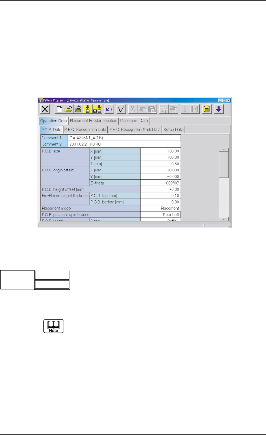
(A01) P.C.B. Data
Fig. 3B7 Edit Window (Example)
(A01_01) Comment 1, 2
Comments on the pattern program can be specified in these
text boxes.
Up to 32 characters (alphanumerics and marks) can be
used.
The performance of the machine is not affected by these com-
ments. In other words, it has nothing to do with or without these
comments.
0206-003 2-11
AHB01EDTP
Comment1
Comment2
Fig. 3B8
2.2 Pattern Program Name
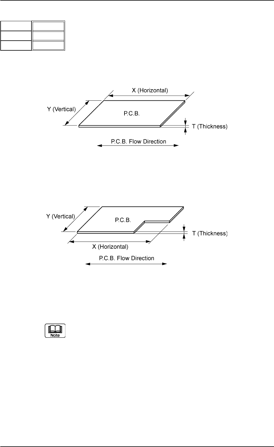
(A01_02) P.C.B. size
X [mm] , Y [mm], T [mm]
Set the dimensions of the P.C.B. to be produced.
Unit: mm
Fig. 3B10
When the P.C.B. has a cutout, the following dimensions must
be entered.
Fig. 3B11
Data Input Range
X: 50 to 330 Y: 50 to 250 T: 0.3 to 2.5
(a) Be sure to set a correct parameter in the "X [mm]" text box
because the set parameter is used to automatically cor-
rect the placement position when a parameter is selected
in the "P.C.B. locate method" text box in the "P.C.B. Trans-
fer Mode Setup" tab sheet.
(b) The set parameter in the "Y [mm]" text box must be used
as a target width for the conveyor width automatic adjust-
ment operation.
(c) The parameter in the "T [mm] (Thickness)" text box must
be used as a target value for the backup table ascending
position when a P.C.B. is clamped by the clamp plates and
positioned.
0206-002 2-12
AHB01EDTP
2.3 Operation Data
130.00
100.00
250.80
X
[mm]
Y [mm]
T
[mm]
Fig. 3B9
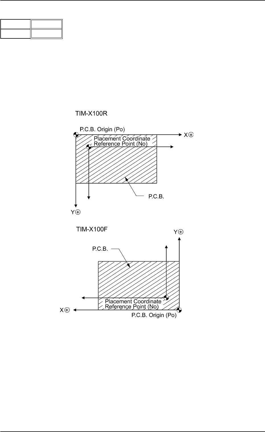
(A01_03) P.C.B. origin offset
X [mm] , Y [mm]
Set the offset values to correct the difference between the
placement coordinate reference point (N
0
) and the P.C.B.
origin (P
0
).
Unit: mm
"Plus" or "Minus" can be set in both X and Y coordinates in
the direction of the correction.
Fig. 3B13 Example "+" (Plus) Direction for Correction
Data Input Range
X: -99.999 to +99.999 Y: -99.999 to +99.999
0206-002 2-13
AHB01EDTP
2.3 Operation Data
X
[mm]
Y [mm]
+00.000
+00.000
Fig. 3B12