3OM-1075-002.pdf - 第295页
2.1.8.2 "Vibratory Stick Feeder" T ab • Sheet Layout When the "Vibratory Stick Feeder" tab is pressed in the "Device Off- set" tab sheet, the following tab sheet appears. Fig. 3E61 "V i…
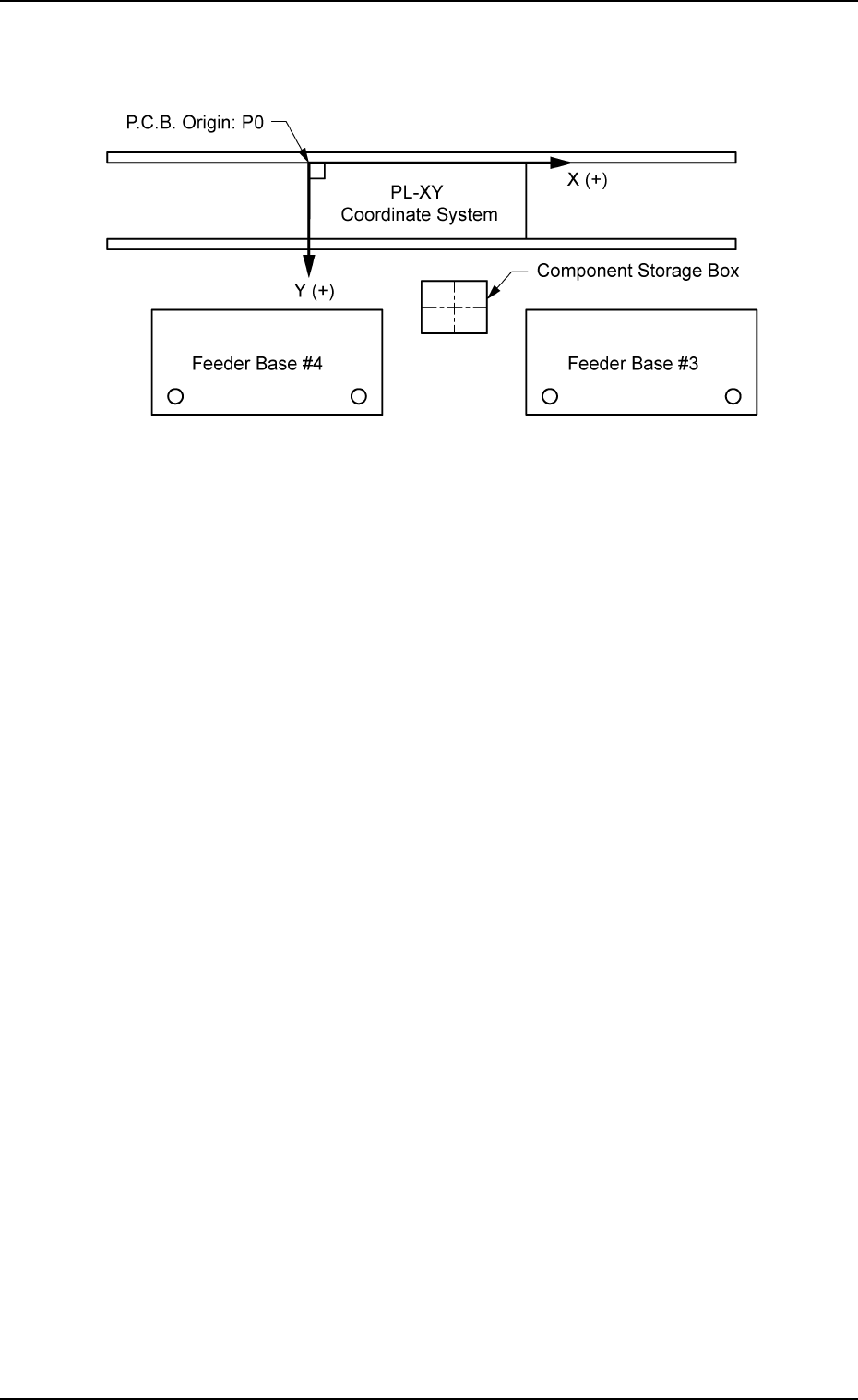
The component storage box is used to store the rejected compo-
nents in the component recognition processing.
Fig. 3E60
When the component storage box is shifted toward the lower right
directiion (viewed from the top), plus values must be enterd in the
"X [mm] (horizontal)" and "Y [mm] (vertical)" text boxes.
When the level (height) of the box is set lower than the design
value, a plus value must be entered in the "L [mm]" text box.
0206-002 5-62
AHB01EDTP
2.1 "Offset Data" Tab
2.1.8.2 "Vibratory Stick Feeder" Tab
• Sheet Layout
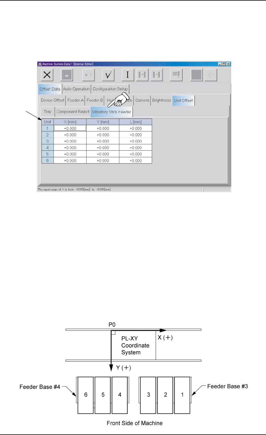
When the "Vibratory Stick Feeder" tab is pressed in the "Device Off-
set" tab sheet, the following tab sheet appears.
Fig. 3E61 "Vibratory Stick Feeder" Tab Sheet
The tab sheet may look different, depending on which options
are selected.
• Sheet Composition
*1 Offset Items
Set the following offset values.
Unit 1 to 6 X [mm] (Horizontal), Y [mm] (Vertical)
This offset data is used to adjust the positional deviations compared
with the design dimensions of Vibratory Stick Units #1 through #6.
The values based on the PL-XY coordinate system must be en-
tered in each text box.
Fig. 3E62
2.1 "Offset Data" Tab
0308-003 5-63 AHB01EDTP
*1

When offset parameters are entered with "+" (plus) signs for "X
[mm]" and "Y [mm]", the head moves in the (+) direction in the
PL-XY coordinate system.
Unit 1 to 6 L [mm] (Height)
The set offset parameters are used to adjust the vertical (height
direction) deviations compared with the design dimensions of Vi-
bratory Stick Units #1 through #6.
When a vibratory stick unit is installed lower than the design value,
plus values must be entered.
2.1 "Offset Data" Tab
01 12-001 5-64 AHB01EDTP