3OM-1075-002.pdf - 第252页
2.1.1.4 "Y-Axis" T ab • Sheet Layout When the "Y-Axis" tab is pressed in the "Device Offset" tab sheet, the following tab sheet appears. Fig. 3E21 "Y-Axis" T ab Sheet • Sheet Compo…

Mark #2 L [mm] (Height)
This offset data is used to adjust the positional deviations (height
direction) compared with the design dimensions of Feeder Bases
#1, #3, and #4 (Rear Side: Feeder Base #1, Front Side: Feeder
Bases #3 and #4).
When the feeder bases are installed lower than the design values, a
plus value must be entered in each text box.
The tilts of the P.C.B. positioning sections on the feeder
bases are calculated based on the X and Y values of Marks
#1 and #2.
01 12-002 5-20
AHB01EDTP
2.1 "Offset Data" Tab
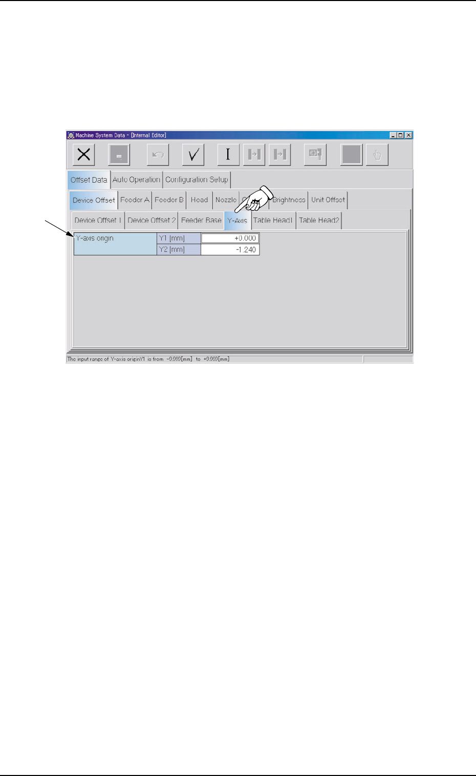
2.1.1.4 "Y-Axis" Tab
• Sheet Layout
When the "Y-Axis" tab is pressed in the "Device Offset" tab sheet,
the following tab sheet appears.
Fig. 3E21 "Y-Axis" Tab Sheet
• Sheet Composition
*1 Offset Items
Set the following offset values.
Y-axis origin Y1 [mm] and Y2 [mm]
This offset data is used to adjust the parallelism between the P.C.B.
positioning chute and the beam (X1 and X2 axes) when the Y axis is
zeroed.
0308-004 5-21
AHB01EDTP
*1
2.1 "Offset Data" Tab
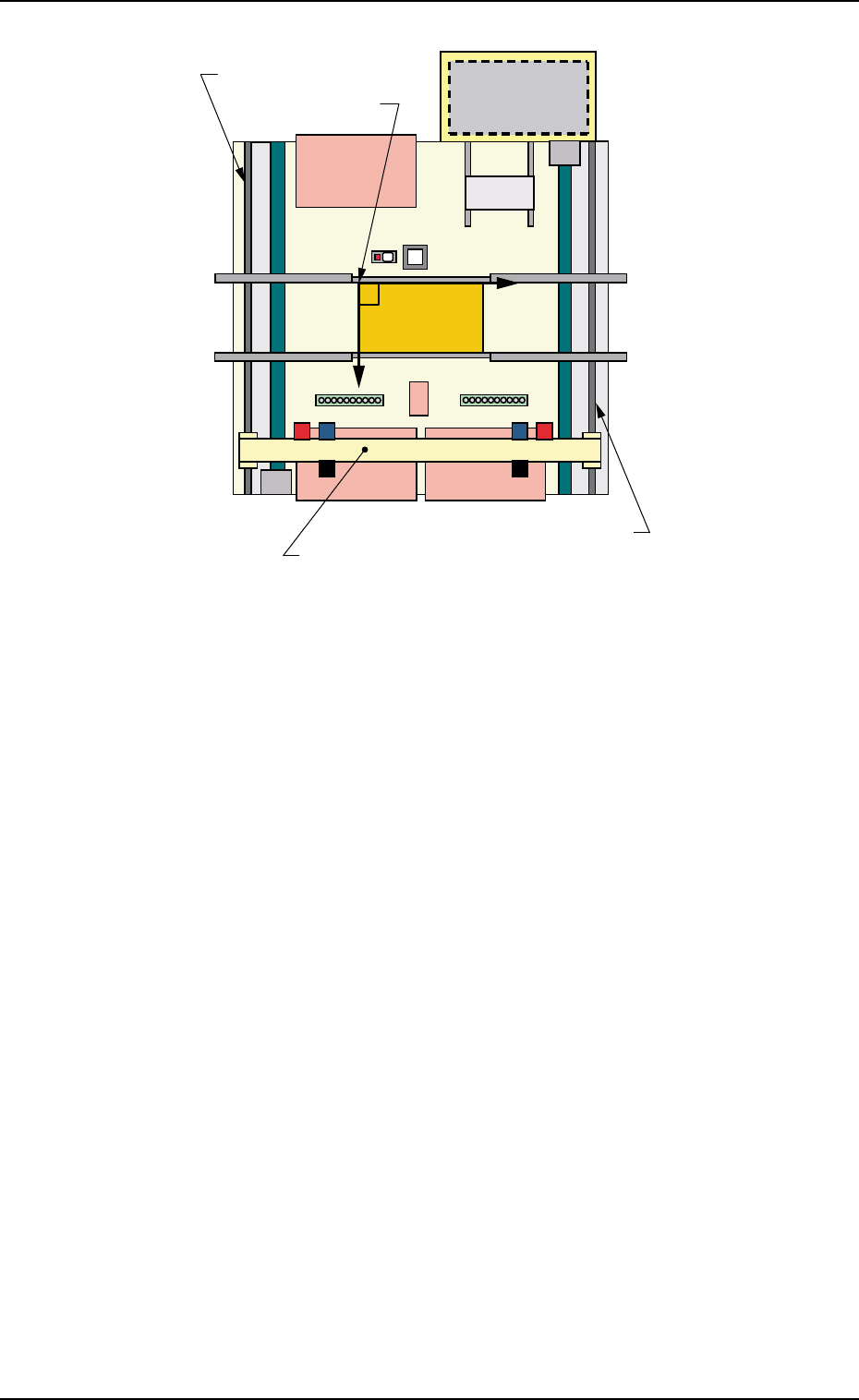
Fig. 3E22
0206-003 5-22
AHB01EDTP
P.C.B. Origin:
P0
Y-Axis Linear Guide
Beam (X1 and X2 Axes)
Y-Axis Linear Guide
Y(+)
X(+)
2.1 "Offset Data" Tab