3OM-1075-002.pdf - 第303页
0206-002 5-71 AHB01EDTP 2.2 "Auto Operation" T ab Component recog camera position correct Mode, Mount counts Mode "Correct" or "No Correct" can be selected to determine whether or not the co…
0206-002 5-70 AHB01EDTP
2.2 "Auto Operation" Tab
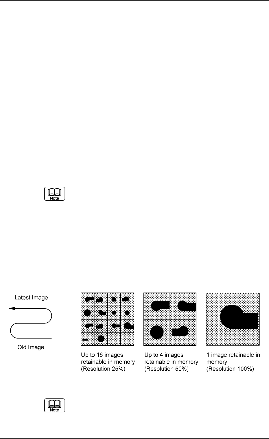
Recog error image save
Mode, Object, Select, # of images
Set parameters in the "Object", "Select", and "# of images" text
boxes to analyze the cause of a recognition error in comparison
with the error image on the monitor.
When "Save" is set in the "Mode" text box, the image which
matches the parameters in the "Object" and "Select" text boxes
is stored in memory of the recognition board. The image is stored
at the resolution specified in the "# of images" text box.
Mode
Select "Not Save", "Save (Recog NG)", "Save (Recog OK)", or
"Save (Recog OK/NG)".
Object
Select "All Recog Error", "Component Recog Error", or "P.C.B.
Recog Error".
Select
Select "None", "Camera No.", "Component ID", or "Feeder No.".
(a) When "Component ID" is selected, a component ID name
must be specified.
(b) When "Feeder No." is selected, a "Fdr. No." must be speci-
fied.
(c) The parameter set in the "Select" text box becomes valid
only for those related to component recognition errors.
Setting of "Recog error image save" for P.E.C. recognition
errors becomes unconditional.
# of images
16 (25% Resoln), 4 (50% Resoln), 1 (100% Resoln)
Fig. 3E65
The image data stored in memory is cleared when the power
switch of the machine is turned off.
0206-002 5-71 AHB01EDTP
2.2 "Auto Operation" Tab
Component recog camera position correct
Mode, Mount counts
Mode
"Correct" or "No Correct" can be selected to determine whether
or not the component recognition camera position should be cor-
rected periodically.
It is recommended to set "Correct" in normal cases.
Mount counts
Press the [TenKey] button on the main menu bar to open the
"TenKey" edit window and enter the following numerical value.
"0" : No automatic correction operation is performed for
each number of components to be placed.
"1" to "9999" : Correction is made according to the specified num-
ber of components to be placed.
(a) When "Correct" is set in the "Mode" text box, the correc-
tive actions take place automatically before the P.C.B. is
transferred to the P.C.B. positioning section and the com-
ponent recognition operation is performed.
(b) When the number of components (components to be
placed on a production P.C.B.) per beam is smaller than
the set number of components, the corrective actions do
not take place in the middle of placement operation.
Because the internal counter for interval monitoring is
cleared through the above-described corrective actions
(the actions which take place during P.C.B. positioning),
no corrective actions take place in compliance with the
number of components to be placed on several P.C.B.’s.
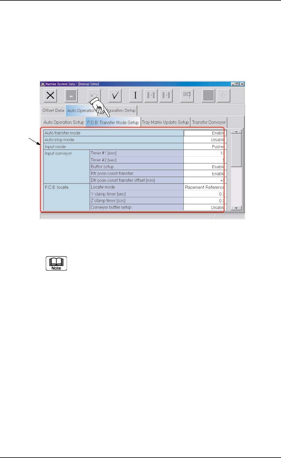
2.2.2 "P.C.B. Transfer Mode Setup" Tab
••
••
• Sheet Layout
When the "P.C.B. Transfer Mode Setup" tab is pressed in the "Auto
Operation" tab sheet, the following tab sheet appears.
Fig. 3E66 "P.C.B. Transfer Mode Setup" Tab Sheet
(Provided with Multi-Layer Tray Feeder 2)
The tab sheet may look different, depending on which options are
selected.
••
••
• Sheet Composition
*1 Items
The following items are displayed.
Auto transfer mode
Set "Enable" or "Disable" in the text box to determine whether or
not the automatic transfer function should be used.
When "Disable" (Standard) is set, P.C.B.
,
s are transferred
as follows
The finished P.C.B. (where components are already placed) on
0308-003 5-72
AHB01EDTP
2.2 "Auto Operation" Tab
*1