3OM-1075-002.pdf - 第124页
0308-002 2-105 AHB01EDTP 4.3 "Placement Feeder Location" T ab • Operation Procedure (1) Select the tab corresponding to the feeder base where the vibratory stick feeders should be allocated. The vibratory stick…
*2 Fdr. No.
Shown under this title are the feeder Nos.
Refer to "4.3.1 "Feeder Base #1", "Feeder Base #3", and
"Feeder Base #4" Tabs" for operations such as addition,
deletion, etc., of the feeder Nos. (Fdr. No.).
*3 Component ID
Displayed are the currently allocated component IDs.
Refer to "4.3.2 "Component ID List" Window" for how to
enter or delete a component ID.
*4 C, Comment, Feeder Alternate, Fdr No.,
Position X [mm], Position Y [mm]
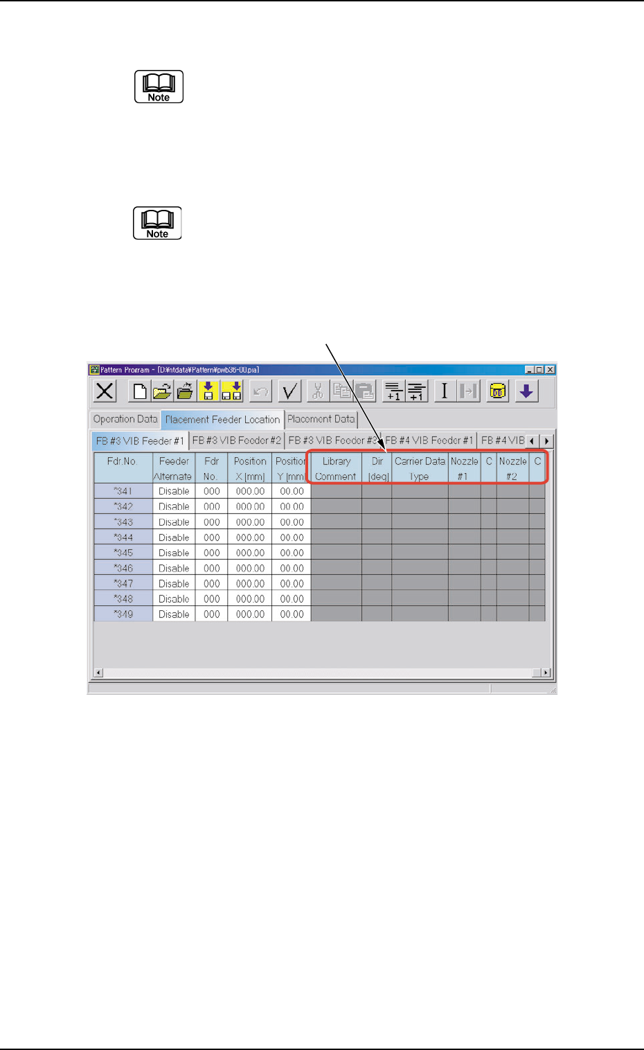
Fig. 3B170 "FB #3 VIB Feeder #1" Tab Sheet
*5 Library Comment, Dir [deg], Carrier Data Type, Nozzle #1, C,
Nozzle #2, and C
Displayed are the parameters specified in the component library.
*5
4.3 "Placement Feeder Location" Tab
0308-002 2-104 AHB01EDTP
0308-002 2-105 AHB01EDTP
4.3 "Placement Feeder Location" Tab
• Operation Procedure
(1) Select the tab corresponding to the feeder base where the vibratory
stick feeders should be allocated.
The vibratory stick feeders can be allocated to Feeder Base #3 or
#4.
Fig. 3B171
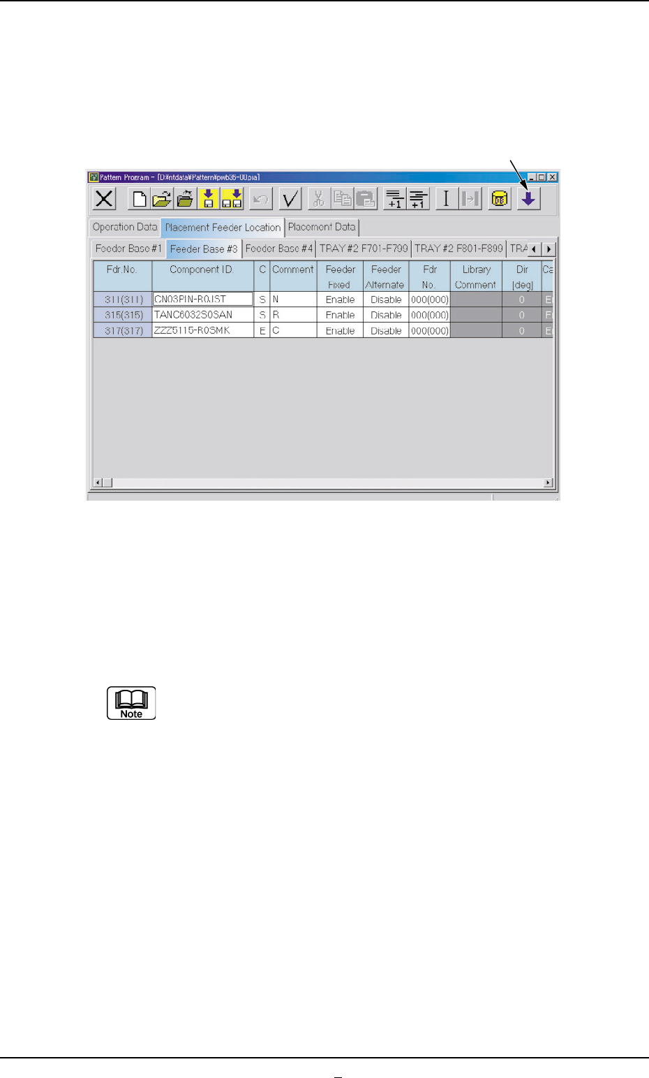
(2) Press the [Open 2nd. Toolbar] icon.
(3) Select the feeder No. (Fdr. No.) where the vibratory stick unit should
be allocated and press the [VIB. STK. UNIT] icon.
"<VIB.STK.UNIT>" appears in the "Component ID." text box of the
reference feeder No. (Fdr. No.).
(a) In the case of a feeder No. (Fdr. No.) where no vibratory
stick unit can be allocated, "The number of feeders has
reached the maximum counts." appears in the corre-
sponding text box.
(b) Up to 3 vibratory feeders can be installed on one feeder
base.
[Open 2nd. Toolbar] Icon
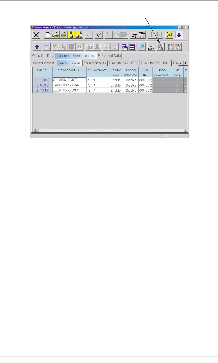
Fig. 3B172
4.3 "Placement Feeder Location" Tab
[VIB. STK. UNIT] Icon
0308-001 2-105-1 AHB01EDTP