3OM-1075-002.pdf - 第273页
2.1.5.3 "Stocker B1" and "Stocker B2" T abs • Sheet Layout When the "Stocker B1" tab is pressed in the "Nozzle" tab sheet, the following tab sheet appears. The navigations similar …
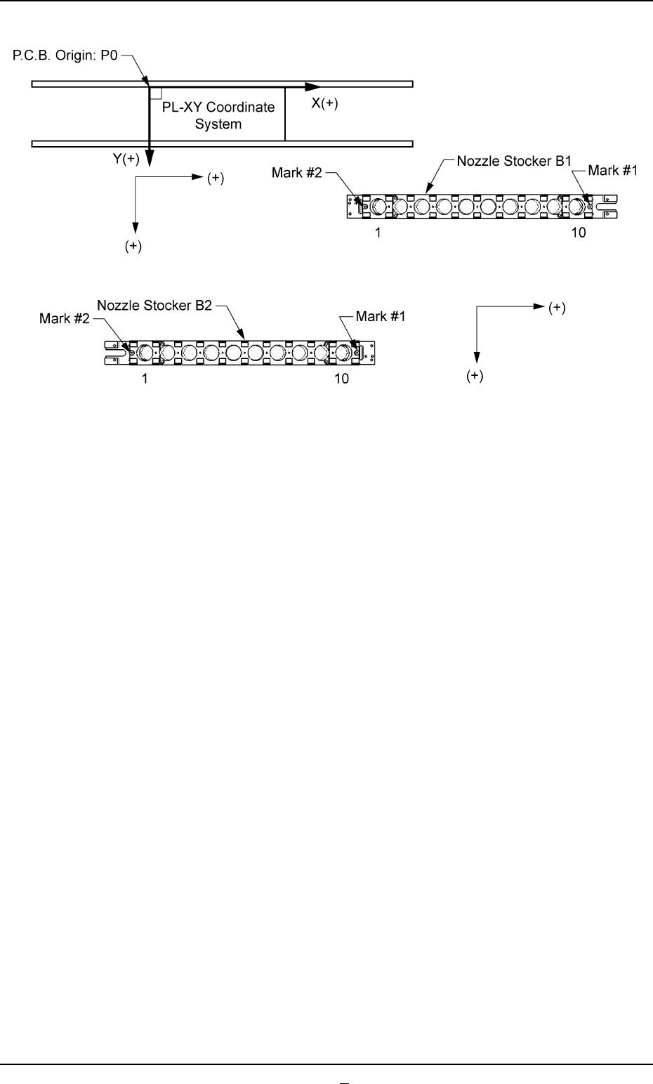
Fig. 3E41
0206-001 5-40-1
AHB01EDTP
2.1 "Offset Data" Tab
2.1.5.3 "Stocker B1" and "Stocker B2" Tabs
• Sheet Layout
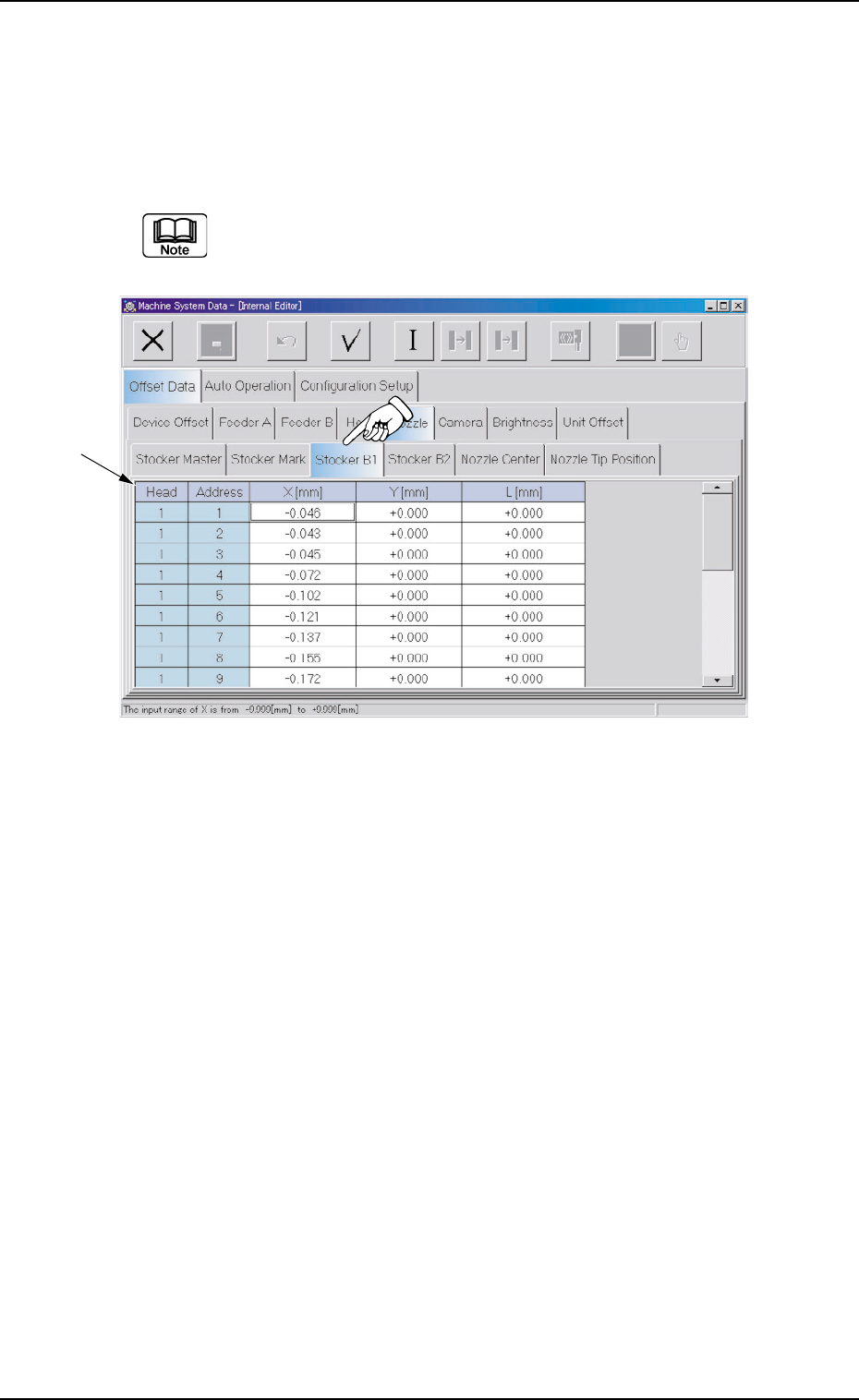
When the "Stocker B1" tab is pressed in the "Nozzle" tab sheet, the
following tab sheet appears.
The navigations similar to those through the "Stocker B1" tab
sheet can be followed through the "Stocker B2" tab sheet.
Fig. 3E42 "Stocker B1" Tab Sheet
• Sheet Composition
*1 Offset Items
Set the following offset values.
Head (1 and 2) and Address (1 through 10)
X [mm] (Horizontal) and Y [mm] (Vertical)
This offset data is used to adjust the positional deviations based on
the design dimensions of the nozzle stocker unit positions (viewed
from the P.C.B. positioning reference X/Y coordinates (PL-XY Coor-
dinates: Origin P0)). The value based on the PL-XY coordinate sys-
tem must be entered in each text box.
*1
0308-004 5-41 AHB01EDTP
2.1 "Offset Data" Tab
When values are entered with a plus (+) sign, the nozzle change
positions are changed to "X (+)" and "Y (+)" shown below.
Fig. 3E43
Head (1 and 2) and Address (1 through 10)
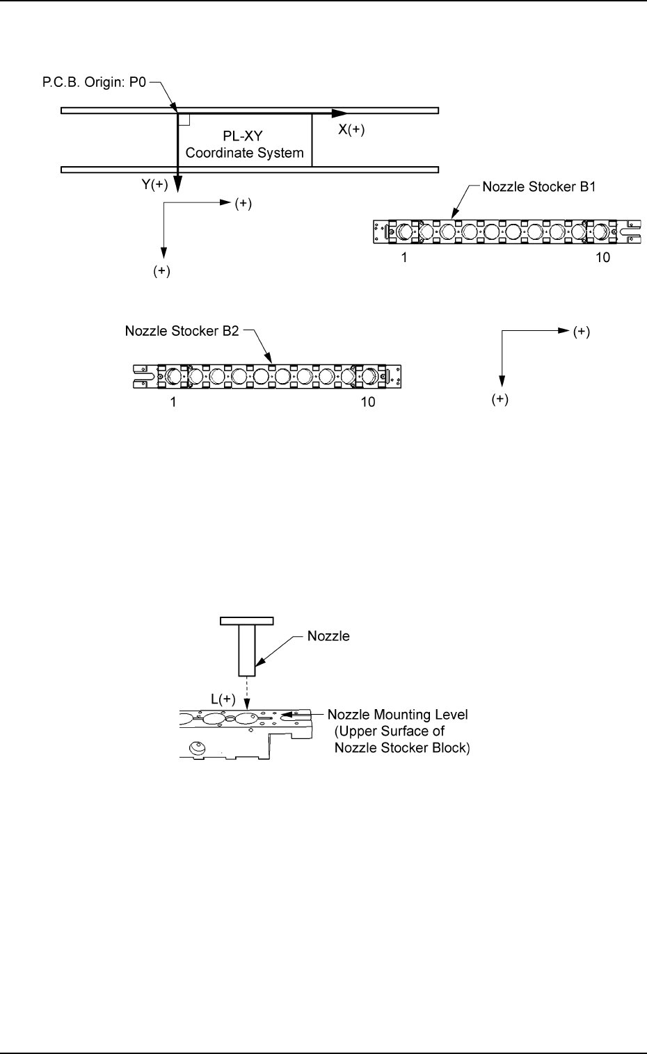
L [mm] (Height)
When an offset value is set with a plus (+) sign, the nozzle change
position (height) is changed to "L (+)" shown below, concluding that
the descending stroke has increased.
Fig. 3E44
2.1 "Offset Data" Tab
0206-003 5-42 AHB01EDTP