3OM-1075-002.pdf - 第22页
1 . 2 Composition of Operation Data This data is used to generally manage the pattern program data. This data is composed of the P .C.B. data, the P .C.B. recognition data, the P .C.B. recognition mark data, and the setu…

1.1.1 Outline of Various Data
The pattern program is composed of the following data.
Operation Data : This data is used to generally manage
the pattern program data.
Placement Feeder Location : This data is used to set parameters
which determine a component ID
(type) to be allocated to each feeder
slot No. (Fdr. No.).
Placement Data : The set parameters (designation of
coordinates and direction) are used for
placement of components allocated in
the placement feeder location data.
1.1.2 Input Procedure of Each Data
Refer to "4. "Pattern Program" Edit Window" for detailed information on
how to enter each parameter.
After entering each parameter, using the network terminal (option), send
it to the main machine.
Pattern Program Data Sheets
Make use of the pattern program data sheets described in "Sec-
tion 6".
0206-002 2-2
AHB01EDTP
1.1 Composition of Pattern Program
1.2 Composition of Operation Data
This data is used to generally manage the pattern program data.
This data is composed of the P.C.B. data, the P.C.B. recognition data,
the P.C.B. recognition mark data, and the setup data.
Refer to "2.3 Operation Data" in "Section 2" for details.
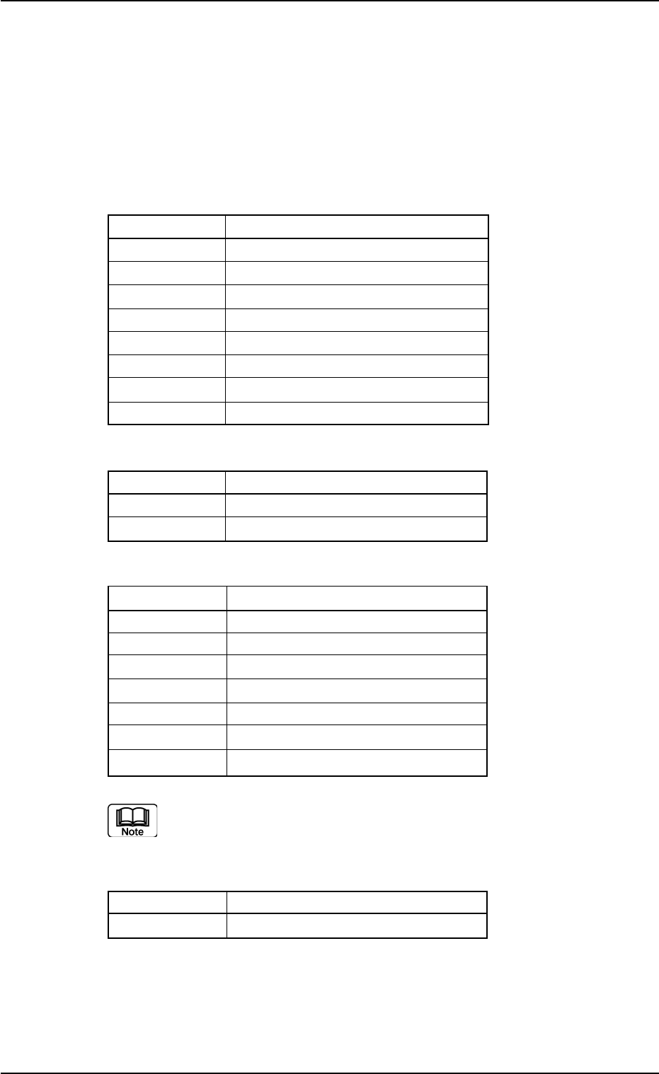
A01 P.C.B. Data Table 3B1
Ref. No. Data Name
A01_01 Comment 1, 2
A01_02 P.C.B. size
A01_03 P.C.B. origin offset
A01_04 P.C.B. height offset [mm]
A01_05 Pre-Placed component thickness
A01_06 Placement mode
A01_07 P.C.B. positioning reference
A01_08 P.C.B. locate
A02 P.E.C. Recognition Data Table 3B2
Ref. No. Data Name
A02_01 P.E.C. recognition function
A02_02 P.E.C. recognition mode Global
A03 P.E.C. Recognition Mark Data Table 3B3
Ref. No. Data Name
A03_01 Mark #
A03_02 Mark Type
A03_03 Mark Size D1 [mm], D2 [mm]
A03_04 Window Size [mm]
A03_05 Mark Image
A03_06 Type Level
A03_07 Recog Algo
Refer to "(A03_08) Fiducial Marks" for detailed information on
each parameter.
A04 Setup Data Table 3B4
Ref. No. Data Name
A04_01 Conveyor width
0206-003 2-3 AHB01EDTP
1.2 Composition of Operation Data

1.3 Composition of Placement Feeder Location Data
The set parameters are used to determine which feeder slot Nos. (Fdr.
Nos.) various types of components should be allocated to.
The allocated component IDs (types) must be specified for each indi-
vidual feeder bases, vibratory stick feeders and multi-layer tray feeders
(option).
When the vibratory stick feeders are used, the allocation of the vibratory
stick units and component IDs must be specified.
Refer to "2.4 Placement Feeder Location Data" in "Section 2" for de-
tails.
B01 Feeder Base #1, #3, #4 Table 3B5
Ref. No. Data Name
B01_01 Fdr. No.
B01_02 Component ID.
B01_03 C
B01_04 Comment
B01_05 Feeder Fixed
B01_06 Feeder Alternate
B01_07 Fdr. No.
B01_08 Library Comment
B01_09 Dir [deg], Carrier Data Type, Width [mm]
B01_10 Nozzle #1, C, Nozzle #2, C
TRAY #2 F701-F799, TRAY #2 F801-F899, TRAY #2 STEP (Option)
Refer to the instruction manual of the multi-layer tray feeders
(option) for details.
B02 FB #3 VIB Feeder #1, #2, #3,
FB #4 VIB Feeder #1, #2, #3
Table 3B6
Ref. No. Data Name
B02_01 Fdr. No.
B02_02 Component ID
B02_03 C
B02_04 Comment
B02_05 Feeder Alternate
B02_06 Fdr. No.
B02_07 Position X [mm], Y [mm]
B02_08 Library Comment
B02_09 Dir [deg], Carrier Data Type
B02_10 Nozzle #1, C, Nozzle #2, C
0308-004 2-4
AHB01EDTP
1.3 Composition of Placement Feeder Location Data