3OM-1075-002.pdf - 第261页
L [mm] (Height) The set parameters are used to correct the variation in the pick-up height of each installed feeder . These parameters are reflected on the descending stroke of the head required to pick up a component. E…
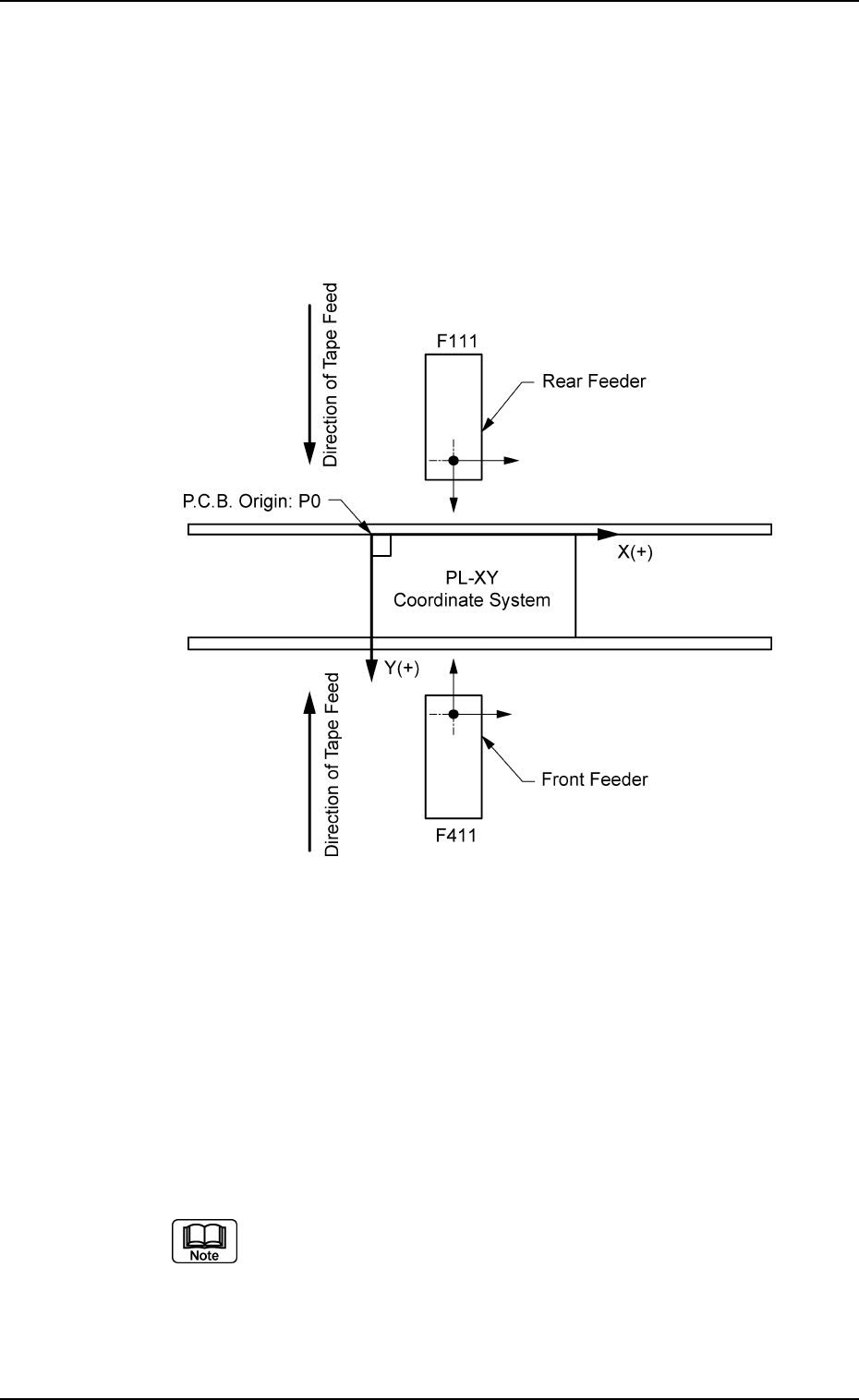
X [mm] (Horizontal) and Y [mm] (Vertical)
This offset data is used to adjust the positional deviations compared
with the design dimensions of the feeder pick-up positions for each
feeder No. (FDR. No.). The value based on the PL-XY coordinate
system must be entered in each text box.
Enter the positional deviations from the pick-up position for each
individual feeders, including the feeder (A) offset data, such that com-
ponents can be picked up at their centers.
Fig. 3E30
When the automatic feeder axis adjustment mode is enabled for
the pick-up position, this data is updated automatically as to pick up
the component center based on the results of the component rec-
ognition for the component picked up during automatic operation.
When the offset parameters are set with a plus (+) sign, the com-
ponent pick-up directions (position) are changed to "X (+)" and "Y
(+)" shown in Fig. 3E30.
This does not apply to even feeder Nos. (even FDR. Nos.).
(Example: F102)
0206-003 5-29
AHB01EDTP
2.1 "Offset Data" Tab
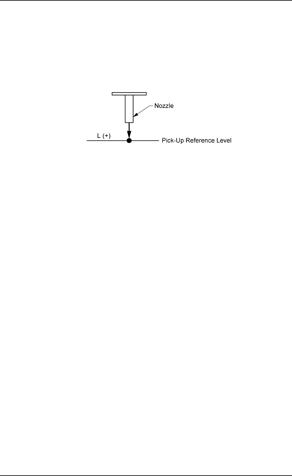
L [mm] (Height)
The set parameters are used to correct the variation in the pick-up
height of each installed feeder.
These parameters are reflected on the descending stroke of the
head required to pick up a component.
Enter the positional deviations from the pick-up position for each
individual feeders, including the feeder (A) offset data.
Fig. 3E31
When a plus value is set as an offset as shown in Fig. 3E31, the
pick-up height is changed, concluding that the nozzle descending
stroke has increased.
0206-003 5-30
AHB01EDTP
2.1 "Offset Data" Tab
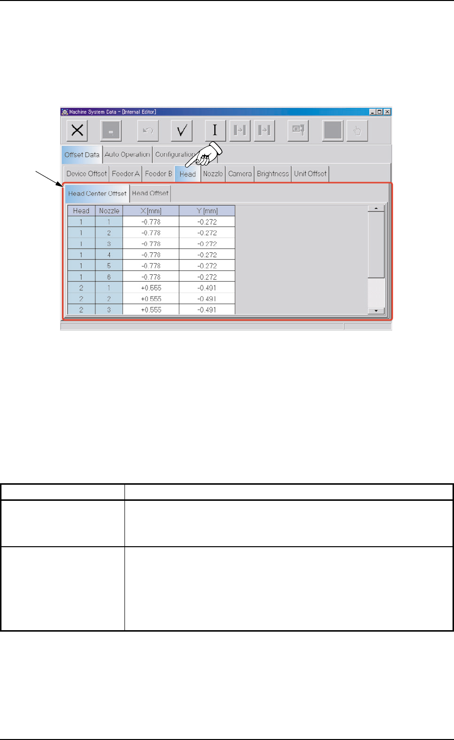
2.1.4 "Head" Tab
• Sheet Layout
When the "Head" tab is pressed in the "Offset Data" tab sheet, the
following tab sheet appears.
Fig. 3E32 "Head" Tab Sheet
• Sheet Composition
*1 Tabs and Tab Sheets
The "Head" tab sheet is provided with the following 2 tabs. When
each tab is pressed, the corresponding tab sheet appears.
Table 3E6
Tabs Description
Head Center Offset The corresponding tab sheet enables the operator to set the deviation
in the distance between the scanning coordinate center of the P.E.C.
camera and the head rotational center.
Head Offset This offset data is used to correct the positional deviation (placement
coordinates) caused due to the deviation of straightness (skew) of
each individual head up/down axis guides.
The set parameters are added to the amount of beam movement
(travel) for component placement.
0308-004 5-31
AHB01EDTP
2.1 "Offset Data" Tab
*1