3OM-1075-002.pdf - 第120页
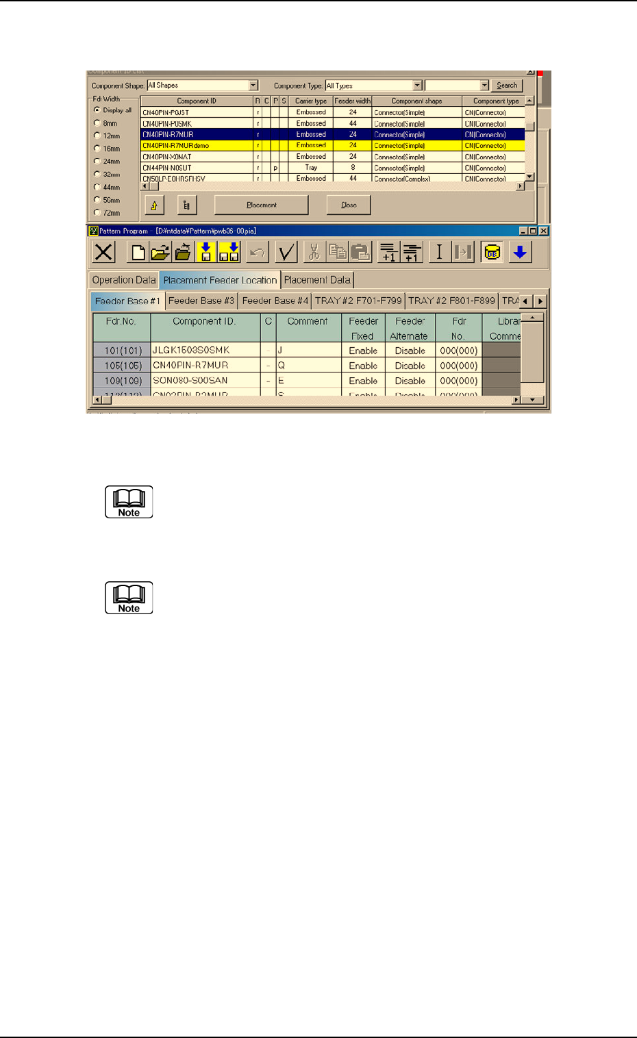
Allocation of Component ID (1) Select the "Feeder Base #" tab where a component ID should be allocated. (2) Select the feeder No. (Fdr . No.) where a component ID should be allocated. The selected line (Fdr . N…
*8 [Search] Button
This button is used to search a component ID.
Fig. 3B166 Arrangement (Example) of "Component ID List" Window
(Provided with Multi-Layer Tray Feeder 2)
The tab sheet may look different, depending on which options
are selected.
• Operation Procedure
It is recommended to drag and drop the "Component ID List"
dialog box at a place where it can be arranged for easier navi-
gation as shown in Fig. 3B166.
Selection of Feeder Width
When several items (functions) are grouped and one of them must be
selected, option buttons are provided in front of the items, allowing you
to choose a single item (function) from a group of options.
A list of components related to the selected feeder width is displayed in
the "List of Component IDs" pane (*6).
Option Buttons
~ : A dot inside the circle indicates that the corresponding function
is selected.
{ : The corresponding function is not selected.
Turning on or off an option button
When a dot is not in an option button, it means that the item (func-
tion) is not selected. When such an option button is pressed, a dot
appears inside the circle, indicating that the item (function) is se-
lected.
When an option button having a dot in the circle is pressed, the dot
disappears, indicating that the selection of the item (function) is can-
celed.
0308-002 2-100 AHB01EDTP
4.3 "Placement Feeder Location" Tab
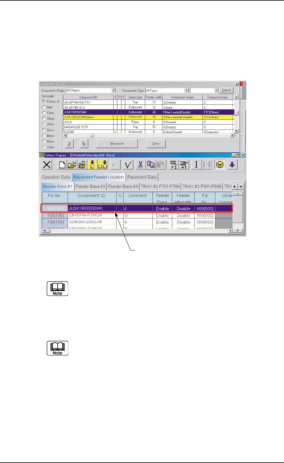
Allocation of Component ID
(1) Select the "Feeder Base #" tab where a component ID should be
allocated.
(2) Select the feeder No. (Fdr. No.) where a component ID should be
allocated.
The selected line (Fdr. No.) turns blue, indicating that it is selected.
Fig. 3B167 Edit Window (Example) (Provided with Multi-Layer Tray Feeder 2)
The tab sheet may look different, depending on which options
are selected.
(3) Select the desired component ID to be allocated in the "Component
ID List" window.
Select the desired options from the "Component Shape" and
"Component Type" drop-down lists and the desired option but-
ton in the "Fdr Width" group box to determine the properties of
the component ID as the requirements to be fulfilled.
(4) Press the [Placement] button.
The selected component ID is allocated to the "Fdr No." line that
has turned blue.
Selected Fdr.No.
0308-002 2-101 AHB01EDTP
4.3 "Placement Feeder Location" Tab
Deletion of Allocated Component ID
(1) Select the desired "Feeder Base #" tab and the feeder No. (Fdr. No.)
of the component to be deleted.
The selected line (Fdr. No.) turns blue, indicating that it is selected.
(2) Select the [Cut] icon on the toolbar. The selected feeder No. (Fdr.
No.) is deleted and the subsequent feeder Nos. are shifted up.
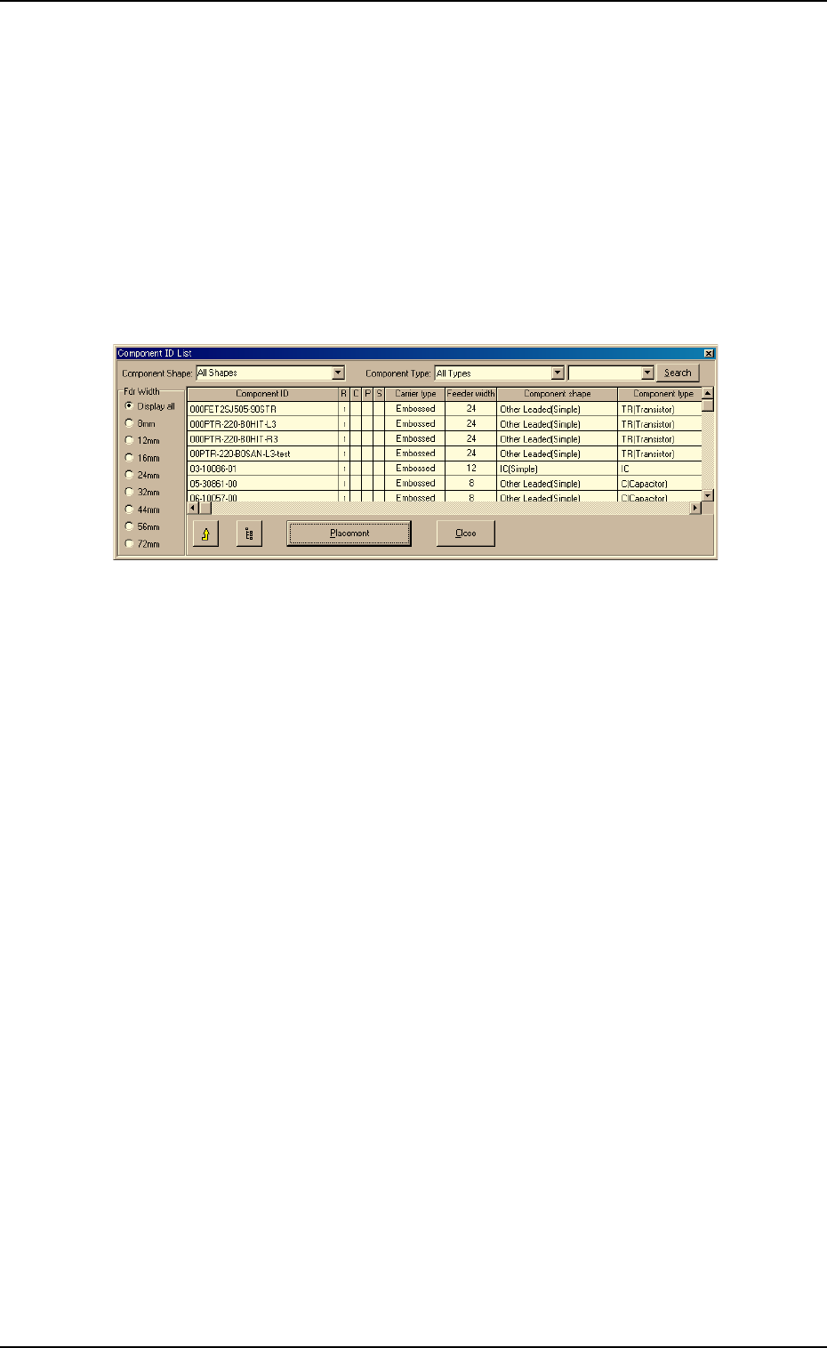
To search for component IDs
(1) Enter the component ID to be searched for, using the wild cards "*"
or "?".
Fig. 3B168
Example: (a) When "AB
∗∗
∗∗
∗" is entered, all component IDs starting with
"AB" can be found and displayed.
(b) When "
∗∗
∗∗
∗CD" is entered, all components ending with
"CD" can be found and displayed.
(c) "AB?DE" is entered, all component IDs substituting "?"
for one of many other characters can be found and dis-
played.
(2) Press the [Search] button.
Only the component IDs that meet the requirements are displayed.
To clear the results of the search operation
(1) Make blank the drop-down list box beside the [Search] button.
(2) Press the [Search] button.
The original condition resumes.
4.3 "Placement Feeder Location" Tab
0308-002 2-102 AHB01EDTP