3OM-1075-002.pdf - 第287页
2.1.7.1 "Component Recog Brightness" T ab This tab sheet must be used only by our service personnel. It is not required to enter any parameters because they are automati- cally taught. • Sheet Layout When the &…
2.1.7 "Brightness" Tab
This tab sheet must be used only by our service personnel.
It is not required to enter any parameters because they are automati-
cally taught.
• Sheet Layout
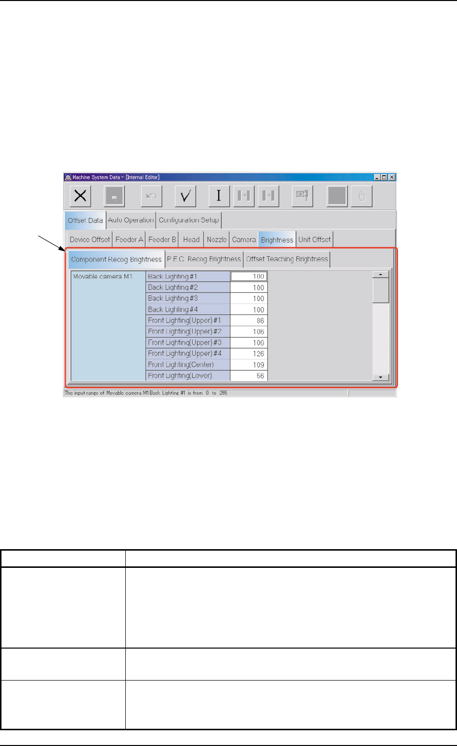
When the "Brightness" tab is pressed in the "Offset Data" tab sheet,
the following tab sheet appears.
Fig. 3E54 "Brightness" Tab Sheet
• Sheet Composition
*1 Tabs and Tab Sheets
The "Brightness" tab sheet is provided with the following 3 tabs.
When each tab is pressed, the corresponding tab sheet appears.
Table 3E9
Tabs Description
Component Recog The corresponding tab sheet enables the operator to set the bright-
Brightness ness of the lighting units on the component recognition cameras (M1,
M2, B1, and B2).
The four lighting units should be adjusted such that they emit lights
having almost the same brightness.
P.E.C. Recog Brightness The corresponding tab sheet enables the operator to set the bright-
ness of the lighting units on P.E.C. Recognition Cameras P1 and P2.
Offset Teaching The corresponding tab sheet enables the operator to set the bright-
Brightness ness (based on the reflection of light emitted from the lighting unit for
offset teaching operations) through automatic teaching operations.
2.1 "Offset Data" Tab
0308-003 5-54 AHB01EDTP
*1
2.1.7.1 "Component Recog Brightness" Tab
This tab sheet must be used only by our service personnel.
It is not required to enter any parameters because they are automati-
cally taught.
• Sheet Layout
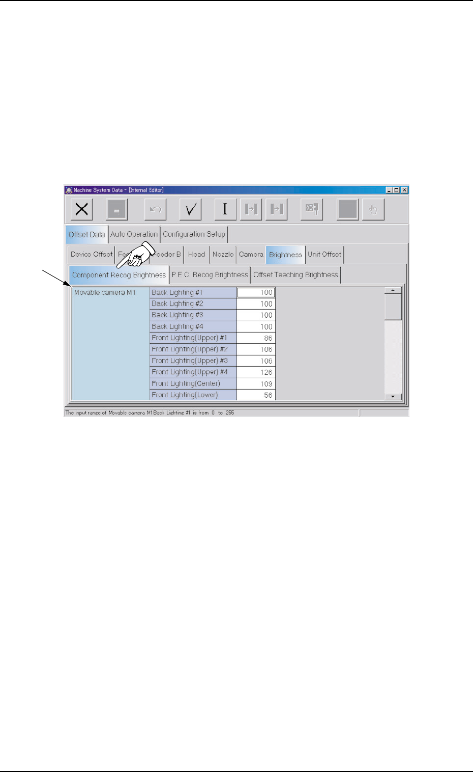
When the "Component Recog Brightness" tab is pressed in the
"Brightness" tab sheet, the following tab sheet appears.
Fig. 3E55 "Component Recog Brightness" Tab Sheet
• Sheet Composition
*1 Offset Items
Set the following offset values.
Movable camera M1 Brightness (Back Lighting #1 through #4,
Front Lighting (Upper) #1 through #4, Front Lighting (Center),
and Front Lighting (Lower))
The specified parameters are used for the component recognition
in which the lighting unit on Head #1 is used.
The machine is provided with the lighting units (back and front light-
ing systems). The lighting units for the back lighting system are lo-
cated above those for the front lighting system.
These brightness values must be determined such that almost the
same brightness (shades of gray) is obtained for each LED (used
for component recognition operations).
"0" (zero) means the darkest and "256" the brightest.
2.1 "Offset Data" Tab
*1
0308-003 5-55 AHB01EDTP

Movable camera M2 Brightness (Back Lighting #1 through #4,
Front Lighting (Upper) #1 through #4, Front Lighting (Center),
and Front Lighting (Lower))
The specified parameters are used for the component recognition
in which the lighting unit on Head #2 is used.
The machine is provided with the lighting units (back and front light-
ing systems). The lighting units for the back lighting system are lo-
cated above those for the front lighting system.
These brightness values must be determined such that almost the
same brightness (shades of gray) is obtained for each LED (used
for component recognition operations).
"0" (zero) means the darkest and "256" the brightest.
Fixed camera A1 Brightness (Back Lighting #1 through #4,
Front Lighting (Upper) #1 through #4, Front Lighting (Center
#1 through #4), and Front Lighting (Lower))
The specified parameters are used for the component recognition
in which the lighting unit on the main machine is used.
The machine is provided with the lighting units (back and front light-
ing systems). The lighting units for the back lighting system are lo-
cated above those for the front lighting system.
These brightness values must be determined such that almost the
same brightness (shades of gray) is obtained for each LED (used
for component recognition operations).
"0" (zero) means the darkest and "256" the brightest.
2.1 "Offset Data" Tab
0206-002 5-56 AHB01EDTP