3OM-1075-002.pdf - 第43页
P .E.C. recognition mode Image When "Enable" is set in "P .E.C. recognition function", set one of the following options as an image recognition mode. Disable : The image recognition function is not us…
1-Point Recognition
Only the X and Y elements are corrected. The θ element
(expansion, etc.) is not corrected.
Fig. 3B30
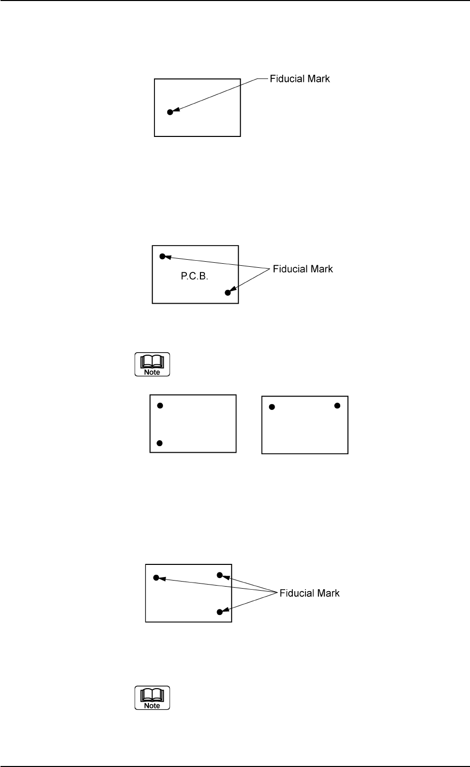
2-Point Recognition
Specify fiducial mark positions so that one fiducial mark is
kept as diagonally away from the other as possible.
Fig. 3B31
Avoid fiducial mark positions aligned horizontally or
vertically with each other as shown below.
Fig. 3B32
3-Point Recognition
Specify fiducial mark positions so that the triangle are formed
by connecting the three points (three fiducial marks) be-
comes as large as possible.
Fig. 3B33
When any two of the three fiducial marks are desig-
nated to be positioned as close as possible to each
other, the results of the correction will be almost the
same as "2-Point Recognition".
0206-003 2-23 AHB01EDTP
2.3 Operation Data

P.E.C. recognition mode Image
When "Enable" is set in "P.E.C. recognition function", set
one of the following options as an image recognition mode.
Disable : The image recognition function is not used.
Enable : The image recognition function is used.
Fig. 3B35
When the global recognition function is used together
with the image recognition function, both recogniz-
ing actions take place but the placement coordinates
are corrected according to the result of the image
recognition.
0206-003 2-24 AHB01EDTP
2.3 Operation Data
P.E.C. recognition mode Image
Fig. 3B34
Disable
P.E.C. recognition mode Local
Select one of the following options to determine whether or
not the fiducial mark on each component placement point
should be recognized.
Disable : The local recognition function is not used.
Enable : The local recognition function is used.
When "Enable" is selected, set the coordinates of
the fiducial marks in (C02_13), (C02_14), and
(C02_15).
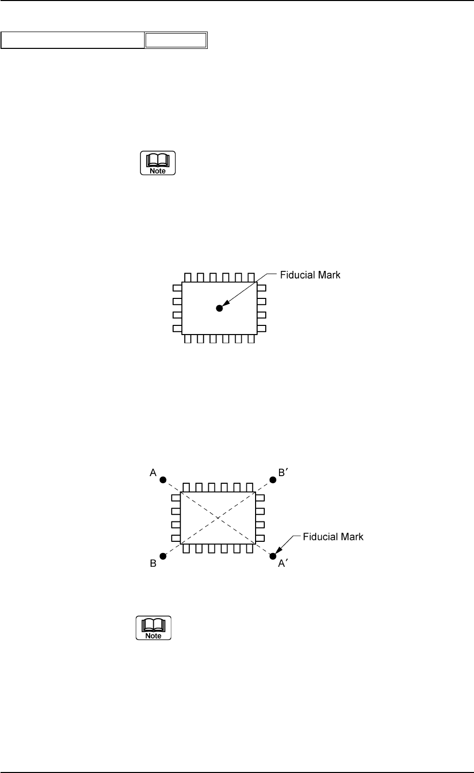
1 Point: Put a fiducial mark on the center of component
placement point or a desired point around the cen-
ter.
Fig. 3B37
2 Point: It is recommended that two points (fiducial marks)
should be located symmetrically on both sides of
the center of the placement position.
Fig. 3B38
(a) When "Enable" is set in the text box, the devia-
tion of each component placement point can
be corrected.
(b) The coordinates and mark code of a fiducial
mark are designated in the placement data (P).
0206-003 2-25
AHB01EDTP
2.3 Operation Data
P.E.C. recognition mode Local
Fig. 3B36
Disable