3OM-1075-002.pdf - 第291页
2.1.7.3 "Offset T eaching Brightness" T ab This tab sheet must be used only by our service personnel. It is not required to enter any parameters because they are automati- cally taught. • Sheet Layout When the …
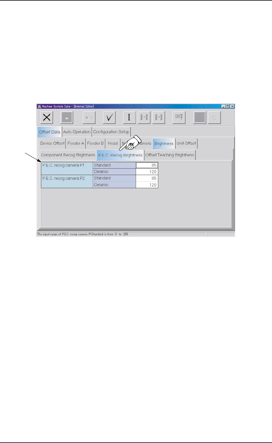
2.1.7.2 "P.E.C. Recog Brightness" Tab
This tab sheet must be used only by our service personnel.
It is not required to enter any parameters because they are automati-
cally taught.
• Sheet Layout
When the "P.E.C. Recog Brightness" tab is pressed in the "Bright-
ness" tab sheet, the following tab sheet appears.
Fig. 3E56 "P.E.C. Recog Brightness" Tab Sheet
• Sheet Composition
*1 Offset Items
Set the following offset values.
P.E.C. recog camera P1 and P2 Brightness (Standard and Ce-
ramic)
The specified parameters are used for the P.C.B. recognition in which
the lighting unit on the beam is used.
There are two P.E.C. recognition cameras - P1 and P2.
Set the brightness values of the LEDs such that the optimum bright-
ness (shades of gray) is obtained for P.C.B. recognition operations.
"0" (zero) means the darkest and "256" the brightest.
2.1 "Offset Data" Tab
0308-003 5-58 AHB01EDTP
*1

2.1.7.3 "Offset Teaching Brightness" Tab
This tab sheet must be used only by our service personnel.
It is not required to enter any parameters because they are automati-
cally taught.
• Sheet Layout
When the "Offset Teaching Brightness" tab is pressed in the "Bright-
ness" tab sheet, the following tab sheet appears.
Fig. 3E57 "Offset Teaching Brightness" Tab Sheet
• Sheet Composition
*1 Offset Items
Set the following offset values.
Offset teaching brightness
The specified parameter is used for the component recognition cam-
era offset teaching operation in which the lighting unit on the main
machine is used.
The brightness value (based on the reflection of light emitted from
the lighting unit for the offset teaching operation) is determined
through the automatic teaching operation.
The brightness value is specified such that the optimum brightness
is obtained.
"0" (zero) means the darkest and "256" the brightest.
0308-003 5-59
AHB01EDTP
*1
2.1 "Offset Data" Tab
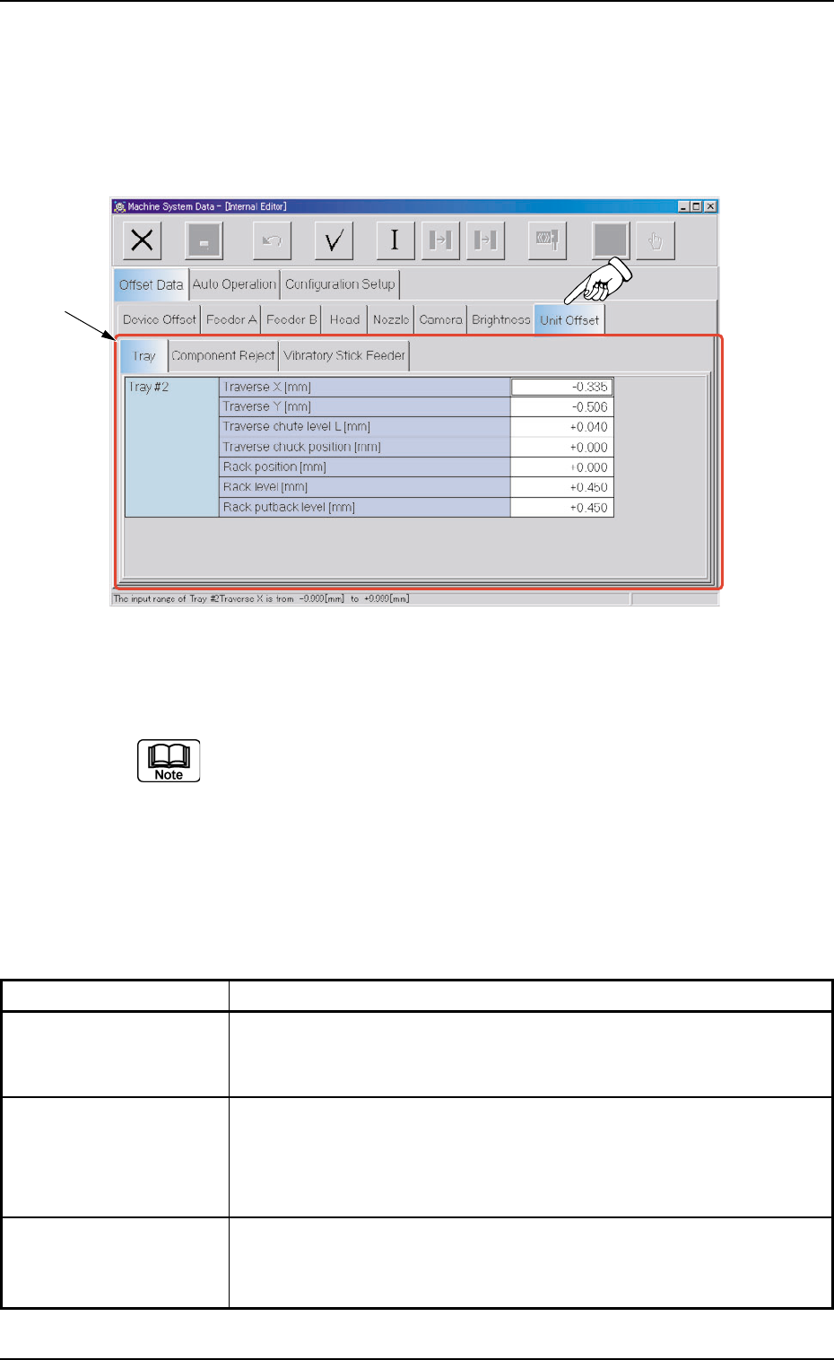
2.1.8 "Unit Offset" Tab
• Sheet Layout
When the "Unit Offset" tab is pressed in the "Offset Data" tab sheet,
the following tab sheet appears.
Fig. 3E58 "Unit Offset" Tab Sheet
(Provided with Multi-Layer Tray Feeder 2)
The tab sheet may look different, depending on which options
are selected.
• Sheet Composition
*1 Tabs and Tab Sheets
The "Unit Offset" tab sheet is provided with the following 3 tab sheets.
Table 3E10
Tabs Description
Tray This is an optional function.
Refer to the instruction manual of the multi-layer tray feeders for de-
tails.
Component Reject The corresponding tab sheet enables the operator to set the offsets
to adjust the positional and vertical (height direction) deviations, com-
pared with the design dimensions (position) of the component stor-
age box located at the center between Feeder Bases #3 and #4.
Vibratory Stick Feeder The corresponding tab sheet enables the operator to set the offset
data for the adjustment of the positional deviations compared with the
design dimensions of Vibratory Stick Units #1 through #6.
2.1 "Offset Data" Tab
*1
0308-003 5-60 AHB01EDTP