3OM-1075-002.pdf - 第71页
(C02_06) H [mm] The component placement height can be corrected. Fig. 3B105 When a parameter is set as "H" data in the last line (last step No.), it becomes invalid because "E" is set in the "C (…
(C02_05) Z=theta
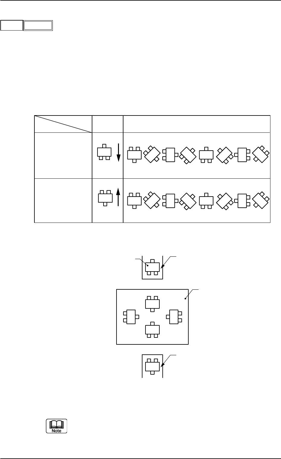
Set angles for component placement.
Data Input Range: 0°00′ to 359°59′
The placement angles must be determined according to the
packaged posture of components on the tape feeder or the
multi-layer tray feeder (option).
Example:
Fig. 3B103
Do not set any angle for component placement in the last line
(last P-No.).
Keep it as "000°00′".
Z
(Angle)
0° 45° 90° 135° 180° 225° 270° 315°
0°
270°
180°
90°
Feeder Base #1
and Multi-Layer
Tray Feeder
(Option)
Packaged
Posture
User Direction
of Tape Feed
Feeder Bases #3
and #4
Packaged
Posture
User Direction
of Tape Feed
Rear View of Machine
Packaged Posture of Component on Feeder
Tape Feeder
Multi-Layer Tray Feeder (Option)
P. C. B .
Front View of Machine
Tape Feeder
0206-003 2-51 AHB01EDTP
2.5 Placement Data
045°00′
Z
Fig. 3B102
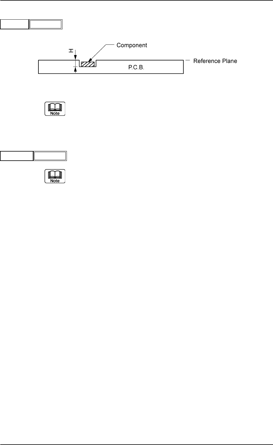
(C02_06) H [mm]
The component placement height can be corrected.
Fig. 3B105
When a parameter is set as "H" data in the last line (last step
No.), it becomes invalid because "E" is set in the "C (Control
Command)" text box.
(C02_07) Fdr. No.
Set the Nos. of the feeders loaded with components.
(a) The feeder Nos. (Fdr. Nos.) to be set here must be speci-
fied in the placement feeder location data.
(b) Do not set any feeder No. in the last line (last step No.).
Keep it as "000".
Fig. 3B106
0206-002 2-52 AHB01EDTP
2.5 Placement Data
H [mm]
Fig. 3B104
+0.00
Fdr. No.
101
(C02_08) C
Enter some of the following control commands.
- (hyphen): This command handles the steps as those
for component placement.
S: This command invalidates the steps specified
as those for component placement.
C: This command invalidates the steps specified
as those for component placement.
Note: As for dispensers, these steps become
valid.
D: This command handles the steps as those for
component placement.
Note: As for dispensers, these steps become
invalid.
E: When placement data (O) is not created, this
shows the end of the steps in the placement data
(P).
P: This shows the end of the steps in the place-
ment data (P) of a repetitive pattern program.
Components are placed in normal sequence.
Q: This shows the end of the steps in the place-
ment data (P) of a repetitive pattern program.
Components are placed in reverse sequence.
0, 1, 2, 3, 4, 5, 6, 7, 8, 9:
These control commands are used to enable
the block sorting function.
See Note (a).
(a) When this block sorting function is used in the following
cases, the productivity will be improved because compo-
nents are placed on the specified areas of unit P.C.B.’s.
• It is required to change the nozzles in the nozzle stocker
for component placement on a certain unit P.C.B. ac-
cording to the repetitive pattern program.
• It is required to change the nozzles in the nozzle stocker
in order to place tall components.
• The productivity deteriorates greatly because the pass
line level is kept high after tall components have been
placed.
(b) Confirm that "0" (zero) is set in the "X [mm]", "Y [mm]",
"Z=theta", "S", "HD","PU",and "Fdr. No." text boxes of the
last line (last step No.) and set "E", "P", or "Q".
0308-004 2-53
AHB01EDTP
2.5 Placement Data
C
Fig. 3B107
-
If a control command other than the following ones is
used, the step becomes invalid.
CAUTION