3OM-1075-002.pdf - 第283页
2.1.6.3 "Component Recog Magnification Gain Level" T ab • Sheet Layout When the "Component Recog Magnification Gain Level" tab is pressed in the "Camera" tab sheet, the following tab sheet a…
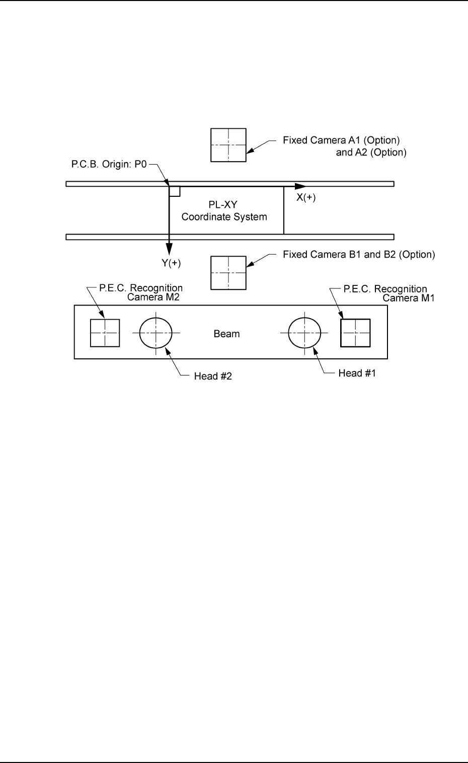
X [mm] (Horizontal), Y [mm] (Vertical), and Z [° ] (Angle)
This offset data is used to adjust the positional and angular devia-
tions compared with the design dimensions of the component rec-
ognition fixed camera center positions (viewed from the P.C.B. po-
sitioning reference (PL-XY Coordinates: Origin P0)). The value based
on the PL-XY coordinate system must be entered in each text box.
Fig. 3E51
This offset data is automatically calculated through teaching opera-
tion which is performed, using the P.E.C. recognition camera on
Head #1.
2.1 "Offset Data" Tab
0206-003 5-50 AHB01EDTP
2.1.6.3 "Component Recog Magnification Gain Level" Tab
• Sheet Layout
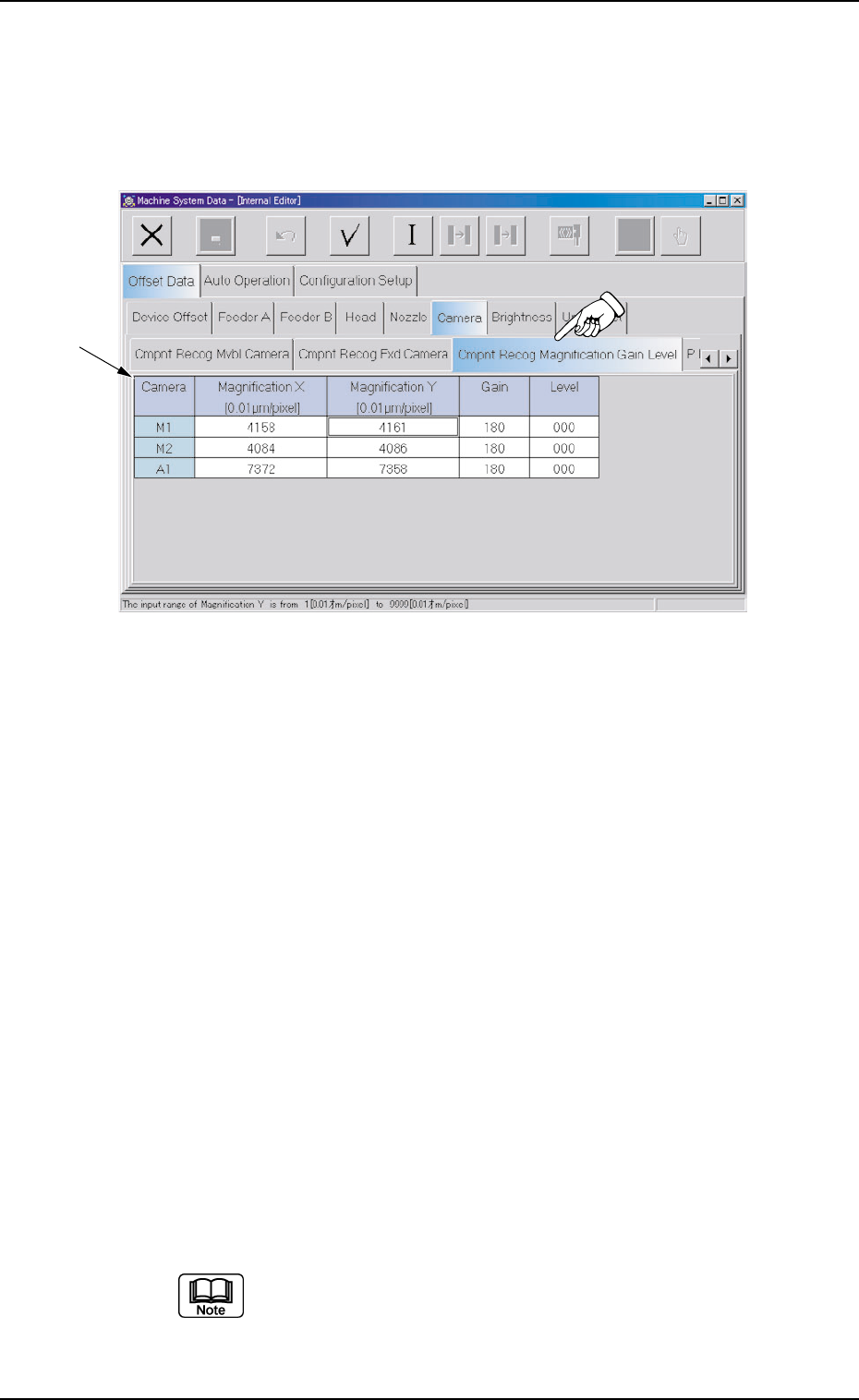
When the "Component Recog Magnification Gain Level" tab is pressed
in the "Camera" tab sheet, the following tab sheet appears.
Fig. 3E52 "Component Recog Magnification Gain Level" Tab Sheet
• Sheet Composition
*1 Offset Items
Set the following offset values.
Magnification X [0.01
µµ
µµ
µm/pixel] (Horizontal) and Magnification
Y [0.01
µµ
µµ
µm/pixel] (Vertical) for Each Camera
These parameters are used to set the magnification of the compo-
nent recognition camera in increments of 0.01 µm per pixel.
The parameters are automatically calculated through teaching op-
eration which is performed, using the jig for magnification measure-
ment.
Gain and Level for Each Camera
These parameters are used to set amplifications at which the im-
age signals of the image captured by the component recognition
cameras are converted into the picture information representing
brightness.
The defaults are "180" for "Gain" and "0" (zero) for "Level" and re-
garded as standard gain and level.
(a) The lower the gain is, the better the contrast becomes.
(b) The smaller the level is, the brighter the whole view
becomes.
2.1 "Offset Data" Tab
*1
0308-004 5-51 AHB01EDTP
2.1.6.4 "P.E.C. Recog Camera" Tab
• Sheet Layout
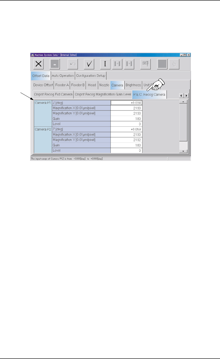
When the "P.E.C. Recog Camera" tab is pressed in the "Camera"
tab sheet, the following tab sheet appears.
Fig. 3E53 "P.E.C. Recog Camera" Tab Sheet
• Sheet Composition
*1 Offset Items
Set the following offset values.
Z [deg] for Each Camera (P1 and P2)
The set parameters are used to adjust the horizontal swing of the
P.E.C. recognition cameras on the beam.
Set parameters representing the angular deviations in the scanning
coordinates of the cameras based on the P.C.B. positioning X/Y
coordinates (PL-XY coordinates: Origin P0).
When the camera scanning coordinates shift to the P.C.B. position-
ing X/Y coordinates system counterclockwise, the sign becomes
"Plus".
2.1 "Offset Data" Tab
0308-004 5-52 AHB01EDTP
*1