3OM-1075-002.pdf - 第250页
Fig. 3E20 When Feeder Bases #1 and #4 are located as shown in Fig. 3E20, minus values must be specified for both X and Y . Mark #1 L [mm] (Height) This offset data is used to adjust the positional deviations (height dire…
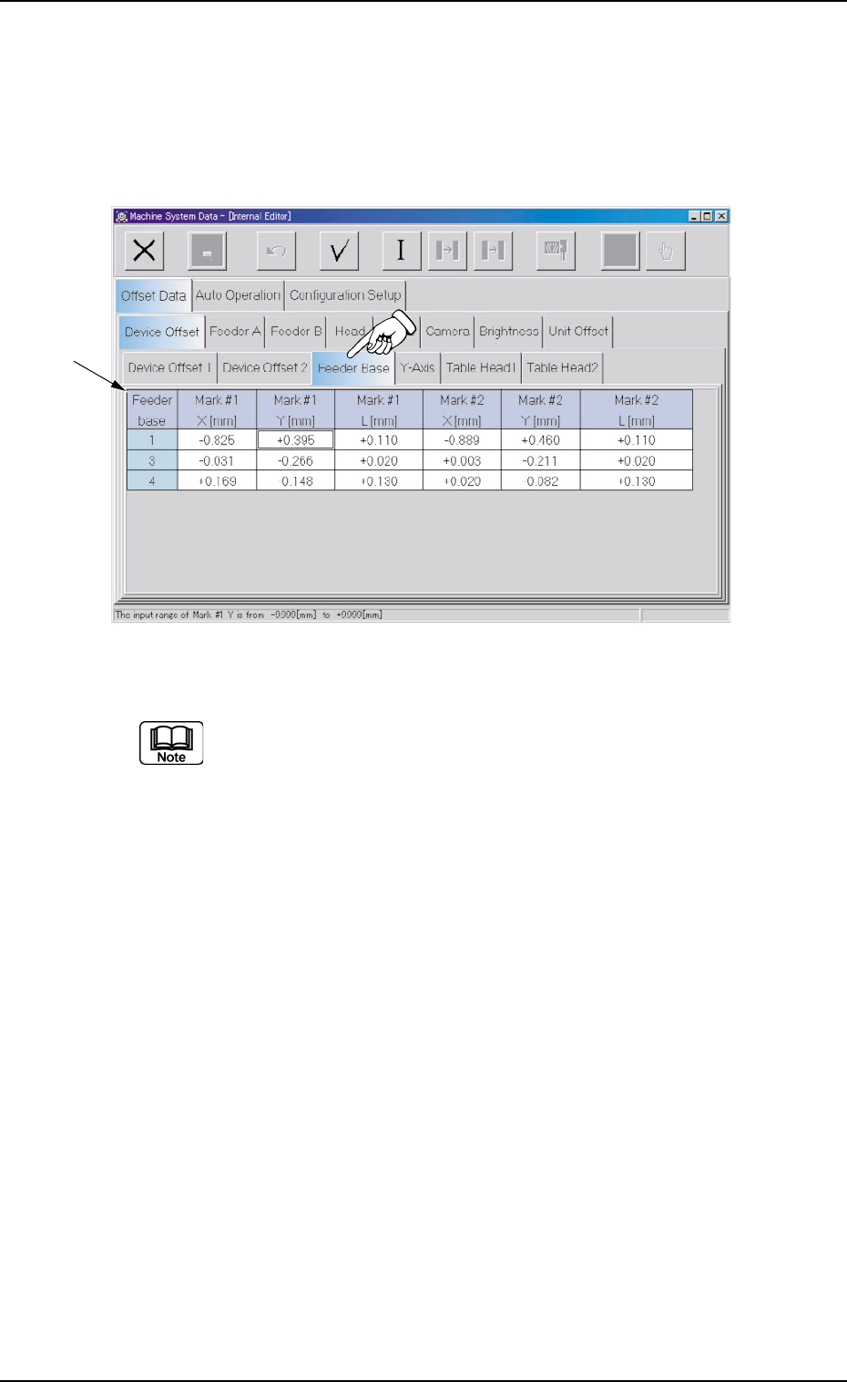
2.1.1.3 "Feeder Base" Tab
• Sheet Layout
When the "Feeder Base" tab is pressed in the "Device Offset" tab
sheet, the following tab sheet appears.
Fig. 3E19 "Feeder Base" Tab Sheet (Provided with Multi-Layer Tray Feeder 2)
The tab sheet may look different, depending on which options are
selected.
• Sheet Composition
*1 Offset Items
Set the following offset values for each individual feeder bases (#1,
#3, and #4).
Mark #1 X [mm] (Horizontal) and Mark #1 Y [mm] (Vertical)
This offset data is used to adjust the positional deviations compared
with the design dimensions of Feeder Bases #1, #3, and #4 (Rear
Side: Feeder Base #1, Front Side: Feeder Bases #3 and #4). The
value based on the PL-XY coordinate system must be entered in
each text box.
As for "Mark #1 X [mm]" and "Mark #1 Y [mm]", the deviations are
calculated through recognition operation (using the P.E.C. camera)
on Fiducial Mark #1.
0308-004 5-18
AHB01EDTP
*1
2.1 "Offset Data" Tab
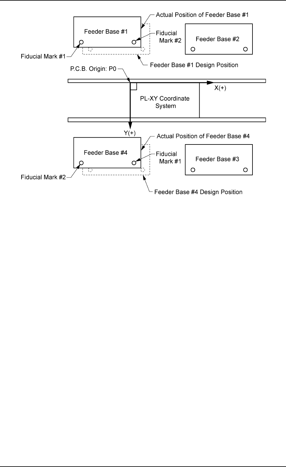
Fig. 3E20
When Feeder Bases #1 and #4 are located as shown in Fig. 3E20,
minus values must be specified for both X and Y.
Mark #1 L [mm] (Height)
This offset data is used to adjust the positional deviations (height
direction) compared with the design dimensions of Feeder Bases
#1, #3, and #4 (Rear Side: Feeder Base #1, Front Side: Feeder
Bases #3 and #4).
When the feeder bases are installed lower than the design values, a
plus value must be entered in each text box.
Mark #2 X [mm] (Horizontal) and Mark #2 Y [mm] (Vertical)
This offset data is used to adjust the positional deviations compared
with the design dimensions of Feeder Bases #1, #3, and #4 (Rear
Side: Feeder Base #1, Front Side: Feeder Bases #3 and #4). The
value based on the PL-XY coordinate system must be entered in
each text box.
As for "Mark #2 X [mm]" and "Mark #2 Y [mm]", the deviations are
calculated through recognition operation (using the P.E.C. camera)
on Fiducial Mark #2.
0206-003 5-19
AHB01EDTP
2.1 "Offset Data" Tab

Mark #2 L [mm] (Height)
This offset data is used to adjust the positional deviations (height
direction) compared with the design dimensions of Feeder Bases
#1, #3, and #4 (Rear Side: Feeder Base #1, Front Side: Feeder
Bases #3 and #4).
When the feeder bases are installed lower than the design values, a
plus value must be entered in each text box.
The tilts of the P.C.B. positioning sections on the feeder
bases are calculated based on the X and Y values of Marks
#1 and #2.
01 12-002 5-20
AHB01EDTP
2.1 "Offset Data" Tab