3OM-1075-002.pdf - 第93页
Order of Component Placement Pattern 1 (C1 Æ C2) Æ Pattern 2 (C1 Æ C2) Æ Pattern 3 (C1 Æ C2) Æ Pattern 3 (C3 Æ C4) Æ Pattern 2 (C3 Æ C4) Æ Pattern 1 (C3 Æ C4) Æ Pattern 1 (C5 Æ C6) Æ Pattern 2 (C5 Æ C6) Æ Pattern 3 (C5 Æ…
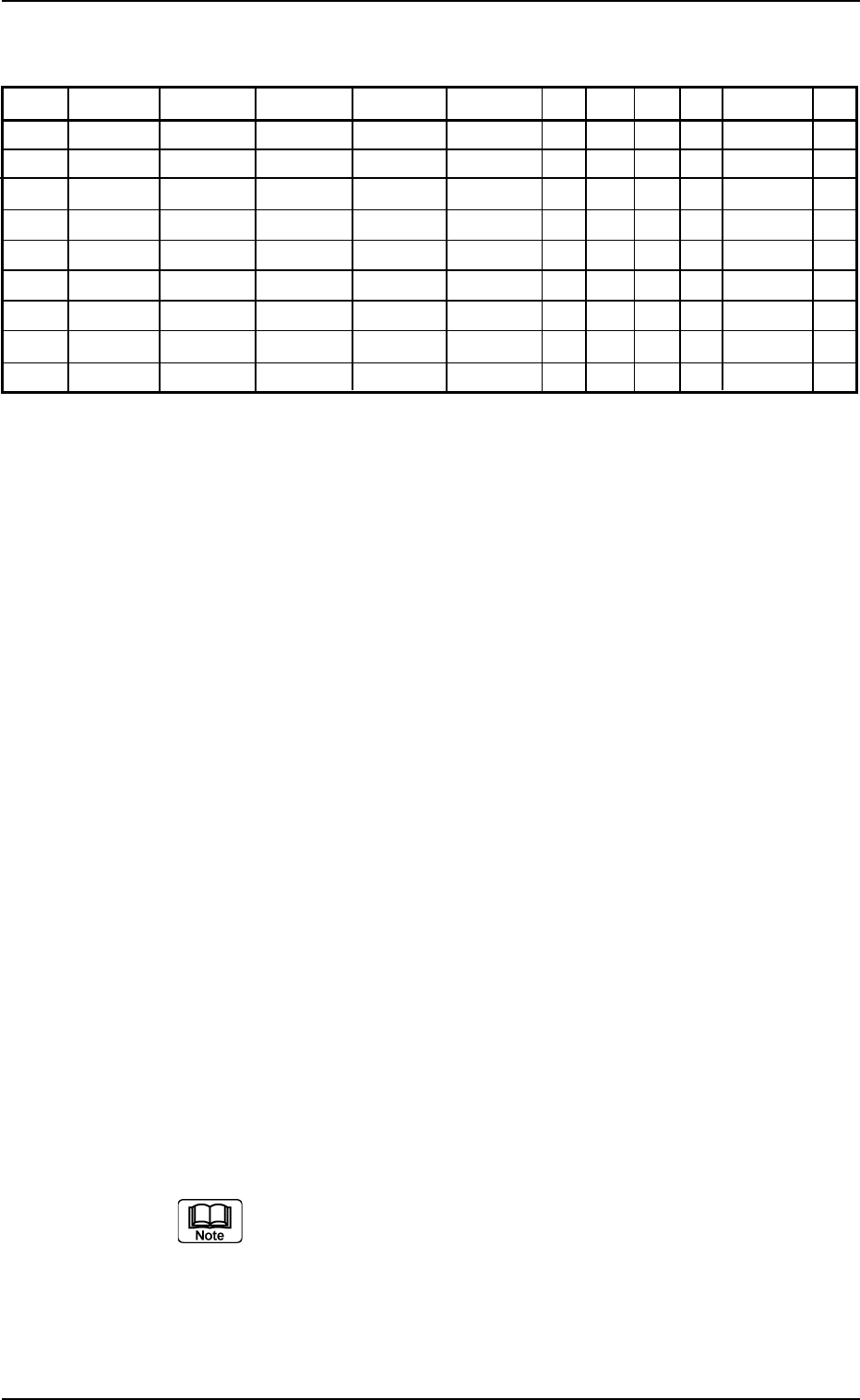
(2) Creation of Placement Data (P-data)
Tabl 3B31
P-No. X [mm] Y [mm] Z H [mm] Fdr. No. C S HD PU Comment V
1X
1
Y
1
Z
1
+0.00 XXX - - 2 0 C1 00
2X
2
Y
2
Z
2
+0.00 XXX - - 1 0 C2 00
3 000.00 000.00 000°00’ +0.00 000 1 - 0 0 00
4X
3
Y
3
Z
3
+0.00 XXX - - 2 0 C3 00
5X
4
Y
4
Z
4
+0.00 XXX - - 1 0 C4 00
6 000.00 000.00 000°00’ +0.00 000 2 - 0 0 00
7X
5
Y
5
Z
5
+0.00 XXX - - 2 0 C5 00
8X
6
Y
6
Z
6
+0.00 XXX - - 1 0 C6 00
9 000.00 000.00 000°00’ +0.00 000 P - 0 0 00
Procedure
(2-1) Classify the components that require the same outside diam-
eters of the nozzles into one group.
Set the grouped components that require the smallest outside
diameter (nozzle) in the smallest P-No. step.
In the above example, C1 and C2 are set in P-Nos. 1 and 2.
(2-2) Set "1" in the "C" text box of P-No. 3 and "0" (zero) in the other
text boxes of the step line.
This step is regarded as a delimit of one group.
Notes: (a) No components are placed for the delimit step.
(b) Any number (0 to 9) can be used as a control com-
mand.
"1" is used in the above example.
(2-3) Keep the same procedure to make each step as follows.
• Set "C3" and "C4" in the "Comment" text boxes of P-Nos. 4
and 5.
• Set "2" in the "C" text box of P-No. 6 and "0" (zero) in the
other text boxes of the step line.
• Set "C5" and "C6" in the "Comment" text boxes of P-Nos. 7
and 8.
(2-4) Create the last step in the same way as a normal program. Be
sure to set "P" as a control command in the "C" text box.
Note: Actual component placement will be made in almost the
reverse sequence as explained below.
Up to 20 groups can be created in one pattern program.
3.5 Repetitive Patterns (Block Sorting Enabled)
0206-003 2-73 AHB01EDTP

Order of Component Placement
Pattern 1 (C1ÆC2) Æ Pattern 2 (C1ÆC2) Æ Pattern 3 (C1ÆC2)
ÆPattern 3 (C3ÆC4) Æ Pattern 2 (C3ÆC4) Æ Pattern 1 (C3ÆC4)
Æ Pattern 1 (C5ÆC6) Æ Pattern 2 (C5ÆC6) Æ Pattern 3 (C5ÆC6)
Æ
Placement Data (O-data)
Follow the normal procedure to create this data.
3.5 Repetitive Patterns (Block Sorting Enabled)
0206-002 2-74 AHB01EDTP
3.6 Repetitive Patterns (Polar Coordinate Conver-
sion Function)
Follow the same procedure as described in "3.4 Repetitive Patterns
(Unit P.C.B. B.B.R. Enabled)" except for "Placement Data (O-data)".
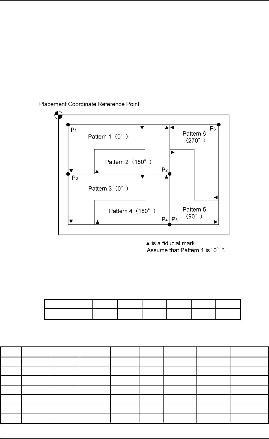
(1) Information on Pattern Program Creation
••
••
• Example of Patterns
Fig. 3B137
••
••
• Coordinates of Each Pattern Origin
Tabl 3B32
Pattern Origin 0
1
0
2
0
3
0
4
0
5
0
6
Coordinates (X
1
, Y
1
)(X
2
, Y
2
)(X
1
, Y
2
)(X
2
, Y
3
)(X
2
, Y
3
)(X
3
, Y
1
)
(2) Creation of Placement Data (O-data)
Tabl 3B33
O-No. X [mm] Y [mm] Z H C Comment B-X [mm] B-Y [mm]
1X
1
Y
1
000°00’ +0.00 - 000.00 000.00
2X
2
Y
2
180°00’ +0.00 - 000.00 000.00
3X
1
Y
2
000°00’ +0.00 - 000.00 000.00
4X
2
Y
3
180°00’ +0.00 - 000.00 000.00
5X
2
Y
3
090°00’ +0.00 - 000.00 000.00
6X
3
Y
1
270°00’ +0.00 - 000.00 000.00
7 000.00 000.00 000°00’ +0.00 E 000.00 000.00
3.6 Repetitive Patterns (Polar Coordinate Conversion Function)
0206-003 2-75 AHB01EDTP