3OM-1075-002.pdf - 第248页
Head1, Nozzle (#1 through #6), Rotation Z [° ] This offset data (offset data for the head rotational axis) is used to adjust the directions of the nozzle clamp springs when each nozzle must be replaced. When the nozzle c…
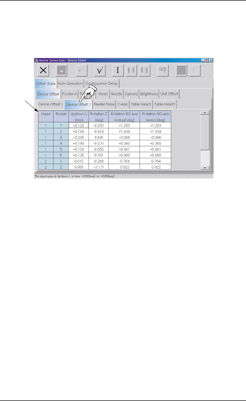
2.1.1.2 "Device Offset 2" Tab
• Sheet Layout
When the "Device Offset 2" tab is pressed in the "Device Offset" tab
sheet, the following tab sheet appears.
Fig. 3E16 "Device Offset 2" Tab Sheet
• Sheet Composition
*1 Offset Items
Set the following offset values.
Head1, Nozzle (#1 through #6), Up/down L [mm]
This offset data (offset data for the origin positions of the head up/
down axis) is used to adjust the distance between the P.C.B. posi-
tioning reference point on the upper surface of a P.C.B. and the
origins of the head #1 up/down axis.
0308-004 5-16
AHB01EDTP
*1
2.1 "Offset Data" Tab
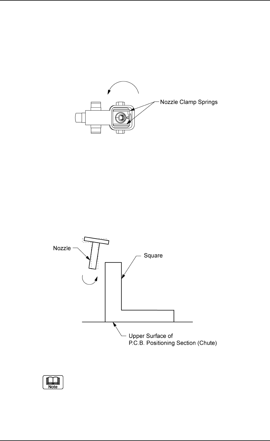
Head1, Nozzle (#1 through #6), Rotation Z [° ]
This offset data (offset data for the head rotational axis) is used to
adjust the directions of the nozzle clamp springs when each nozzle
must be replaced.
When the nozzle clamp springs face the directions shown in Fig.
3E17 (view from the bottom), a plus parameter must be entered as
the offset data.
Fig. 3E17
Head1, Nozzle (#1 through #6), Rotation NC-axis normal [° ],
Rotation NC-axis reverse [° ]
This offset data is used to adjust each nozzle to be directed at a
right angle to the upper surface of the P.C.B. positioning section
when each nozzle (#1 through #6) on Head #1 is replaced.
Two offset parameters must be specified for both normal and re-
verse rotations.
Fig. 3E18
(a) The above square is used just for explanation.
This offset adjustment will be made, using a jig.
(b) Almost the same procedure as Head #1 can be followed to
specify the offset values for each nozzle (#1 through #6) on
Head #2.
0206-003 5-17 AHB01EDTP
2.1 "Offset Data" Tab
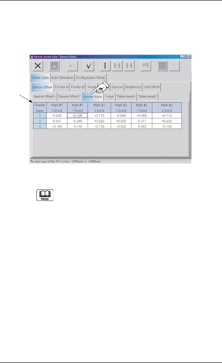
2.1.1.3 "Feeder Base" Tab
• Sheet Layout
When the "Feeder Base" tab is pressed in the "Device Offset" tab
sheet, the following tab sheet appears.
Fig. 3E19 "Feeder Base" Tab Sheet (Provided with Multi-Layer Tray Feeder 2)
The tab sheet may look different, depending on which options are
selected.
• Sheet Composition
*1 Offset Items
Set the following offset values for each individual feeder bases (#1,
#3, and #4).
Mark #1 X [mm] (Horizontal) and Mark #1 Y [mm] (Vertical)
This offset data is used to adjust the positional deviations compared
with the design dimensions of Feeder Bases #1, #3, and #4 (Rear
Side: Feeder Base #1, Front Side: Feeder Bases #3 and #4). The
value based on the PL-XY coordinate system must be entered in
each text box.
As for "Mark #1 X [mm]" and "Mark #1 Y [mm]", the deviations are
calculated through recognition operation (using the P.E.C. camera)
on Fiducial Mark #1.
0308-004 5-18
AHB01EDTP
*1
2.1 "Offset Data" Tab