3OM-1075-002.pdf - 第327页
0206-002 5-94 AHB01EDTP *4 Tip Polarity Set the polarity of the nozzle tip (shape). Enable : Special Nozzle with Polarity (Asymmetrical) Disable : Round Nozzle or the like without Polarity Fig. 3E82 *5 Nozzle Outline X […
0206-002 5-93 AHB01EDTP
3.2 "Nozzle Data" Tab
3.2 "Nozzle Data" Tab
••
••
• Sheet Layout
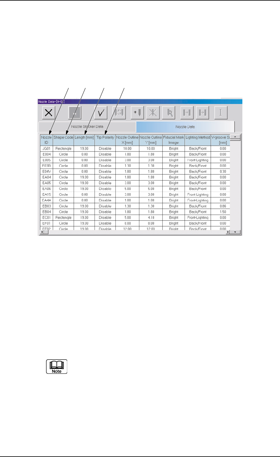
When the "Nozzle Data" tab is pressed in the "Nozzle Data" window,
the following tab sheet appears inside the window.
Fig. 3E81 "Nozzle Data" Tab Sheet
••
••
• Sheet Composition
*1 Nozzle ID
Shown are the nozzle IDs (names).
*2 Shape Code
Set a nozzle shape in each text box.
"Circle" or "Rectangle" can be selected.
In the case of a rectangular nozzle, the pre-rotational pick-up
control (control based on the parameter set in the "Pickup angle
[ ° ]" text box in the "Component Library" edit window) may be
required depending on the packaged posture of a component.
Refer to the instruction manual of the component library for de-
tails.
*3 Length [mm]
Set the nozzle length in this text box.
*1 *2 *3 *4
0206-002 5-94 AHB01EDTP
*4 Tip Polarity
Set the polarity of the nozzle tip (shape).
Enable : Special Nozzle with Polarity (Asymmetrical)
Disable : Round Nozzle or the like without Polarity
Fig. 3E82
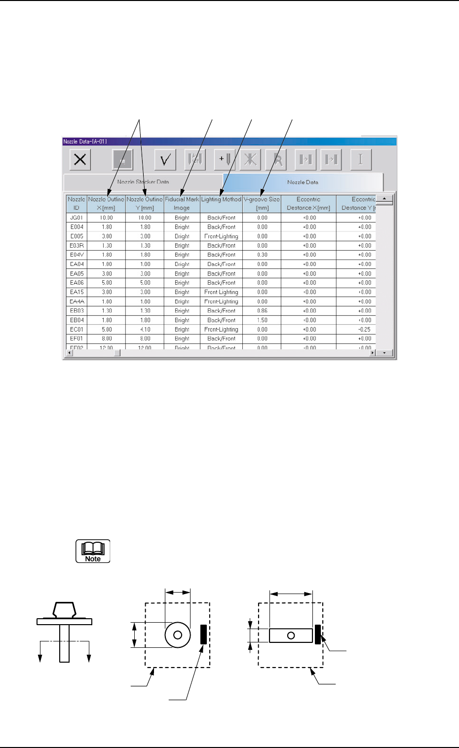
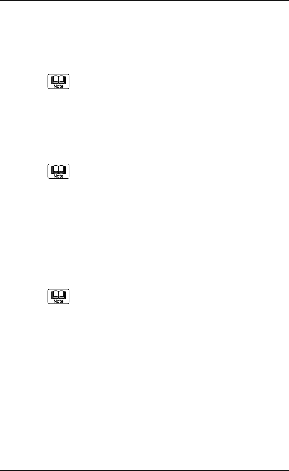
*5 Nozzle Outline X [mm] (Horizontal), Nozzle Outline Y [mm]
(Vertical)
Set the outer dimensions of the nozzle tip section.
Data Input Range
X: 0.00 to 18.00
Y: 0.00 to 18.00
In the case of "Circle", set the same dimensions for "X" and "Y".
In the case of "Rectangle", set Dimensions X and Y.
Fig. 3E83
3.2 "Nozzle Data" Tab
*5 *6 *7 *8
X
Y
X
Y
A′
A
Imprinted Nozzle ID
Imprinted Nozzle ID
Diffusion Plate
Diffusion Plate
01 12-001 5-95 AHB01EDTP
*6 Fiducial Mark Image
Specify how (bright or dark) the image of the nozzle tip is cap-
tured in the front lighting system.
Select one of the following options.
Bright or Dark
(a) The set parameter is required for nozzle masking in the
front lighting system.
(b) In normal cases, set "Bright" in each text box.
*7 Lighting Method
Specify which lighting method can be used for each nozzle.
Select one of the following options.
Back-Lighting, Front-Lighting, Back/Front
"Front-Lighting" must be selected for such a nozzle that the
image of the area other than the nozzle tip appears dark in the
back lighting system.
"Back-Lighting" must be selected for such a nozzle that the
image of the area other than the nozzle tip appears bright in the
front lighting system.
*8 V-Groove Size [mm]
When the V-grooved nozzle is used for cylindrical components, set
the size of the V groove in the corresponding text box.
Data Input Range
00.00 to 18.00
In the case of the nozzle without a V groove, set "0" (zero) in the
corresponding text box.
3.2 "Nozzle Data" Tab