3OM-1075-002.pdf - 第256页
2.1.2.1 "Feeder Base #1", "Feeder Base #2", "Feeder Base #3", and "Feeder Base #4" T abs • Sheet Layout When the "Feeder Base #1" tab is pressed in the "Feeder A&quo…
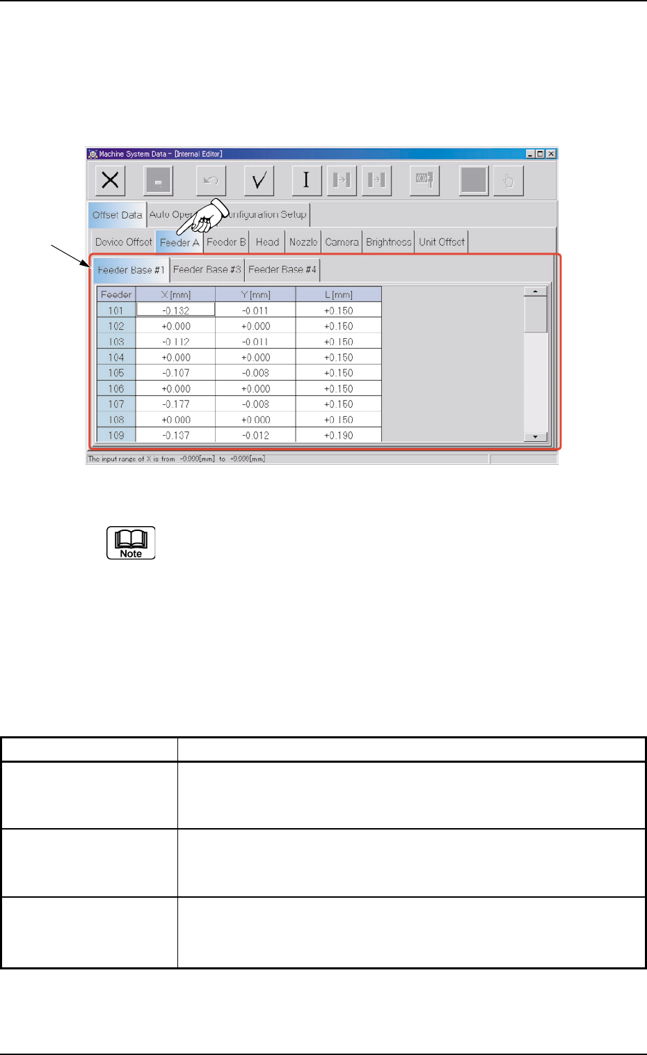
2.1.2 "Feeder A" Tab
• Sheet Layout
When "Feeder A" tab is pressed in the "Offset Data" tab sheet, the
following tab sheet appears.
Fig. 3E24 "Feeder A" Tab Sheet (Provided with Multi-Layer Tray Feeder 2)
The tab sheet may look different, depending on which options are
selected.
• Sheet Composition
*1 Tabs and Tab Sheets
The "Feeder A" tab sheet is provided with the following 3 tab sheets.
When each tab is pressed, the corresponding tab sheet appears.
Table 3E2-2
Tabs Description
Feeder Base #1 The corresponding tab sheet enables the operator to set the offset
data of the pick-up positions at Feeder Nos. 101 through 132 on Feeder
Base #1.
Feeder Base #3 The corresponding tab sheet enables the operator to set the offset
data of the pick-up positions at Feeder Nos. 301 through 332 on Feeder
Base #1.
Feeder Base #4 The corresponding tab sheet enables the operator to set the offset
data of the pick-up positions at Feeder Nos. 401 through 432 on Feeder
Base #1.
0308-004 5-24 AHB01EDTP
*1
2.1 "Offset Data" Tab
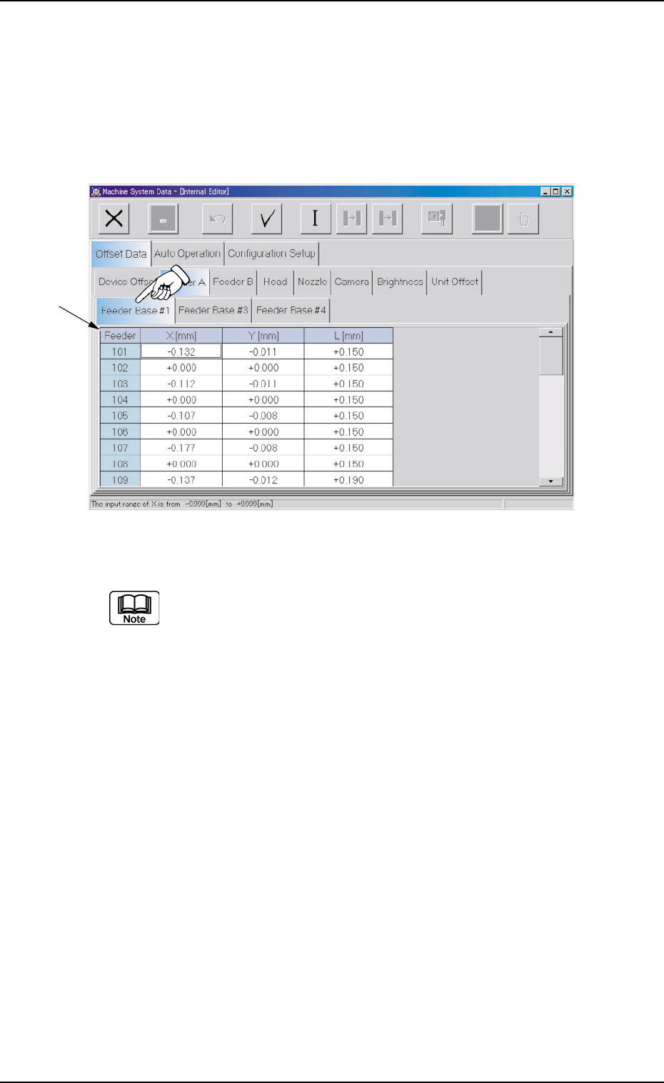
2.1.2.1 "Feeder Base #1", "Feeder Base #2", "Feeder Base #3",
and "Feeder Base #4" Tabs
• Sheet Layout
When the "Feeder Base #1" tab is pressed in the "Feeder A" tab
sheet, the following tab sheet appears.
Fig. 3E25 "Feeder Base #1" Tab Sheet (Provided with Multi-Layer Tray Feeder 2)
(a) The tab sheet may look different, depending on which options are
selected.
(b) Almost the same navigations must be followed for the feeders (101
through 132 on Feeder Base #1, 301 through 332 on Feeder Base
#3, and 401 through 432 on Feeder Base #4) installed on each
feeder base in the "Feeder Base #1", "Feeder Base #3", and
"Feeder Base #4" tab sheets.
• Sheet Composition
*1 Offset Items
Set the following offset values for each feeder (101 through 132 on
Feeder Base #1, 301 through 332 on Feeder Base #3, and 401
through 432 on Feeder Base #4).
0308-004 5-25
AHB01EDTP
*1
2.1 "Offset Data" Tab
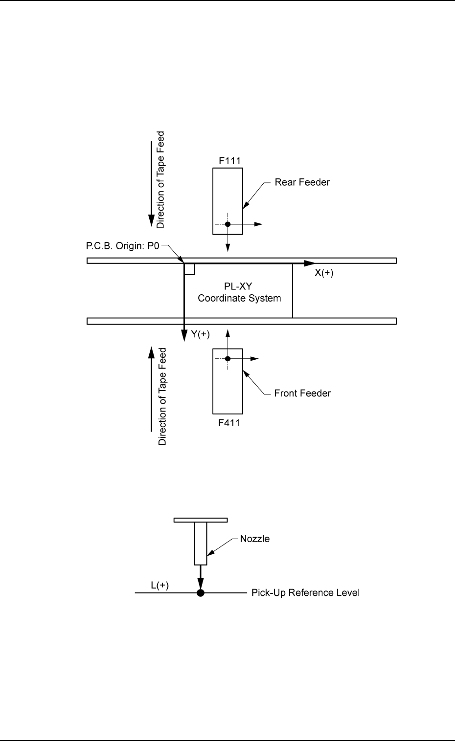
X [mm] (Horizontal) and Y [mm] (Vertical)
This offset data is used to adjust the positional deviations compared
with the design dimensions of the feeder pick-up positions for each
feeder No. (FDR. No.). The value based on the PL-XY coordinate
system must be entered in each text box.
This data is measured and set for the positioning at each feeder’s
pick-up position, using the master jig.
Fig. 3E26
L [mm] (Height)
Fig. 3E27
When a plus value is set as an offset as shown in Fig. 3E27, the
pick-up height is changed, concluding that the nozzle descending
stroke has increased.
0206-003 5-26
AHB01EDTP
2.1 "Offset Data" Tab