3OM-1075-002.pdf - 第78页
(C03_03) Z=theta Set an angle of each pattern. Keep the angle of the reference pattern as "000°00'". In the figure below , "Pattern 1" is regarded as a reference one. Data Input Range: 0°, 90°, 1…
(C03_02) X [mm], Y [mm]
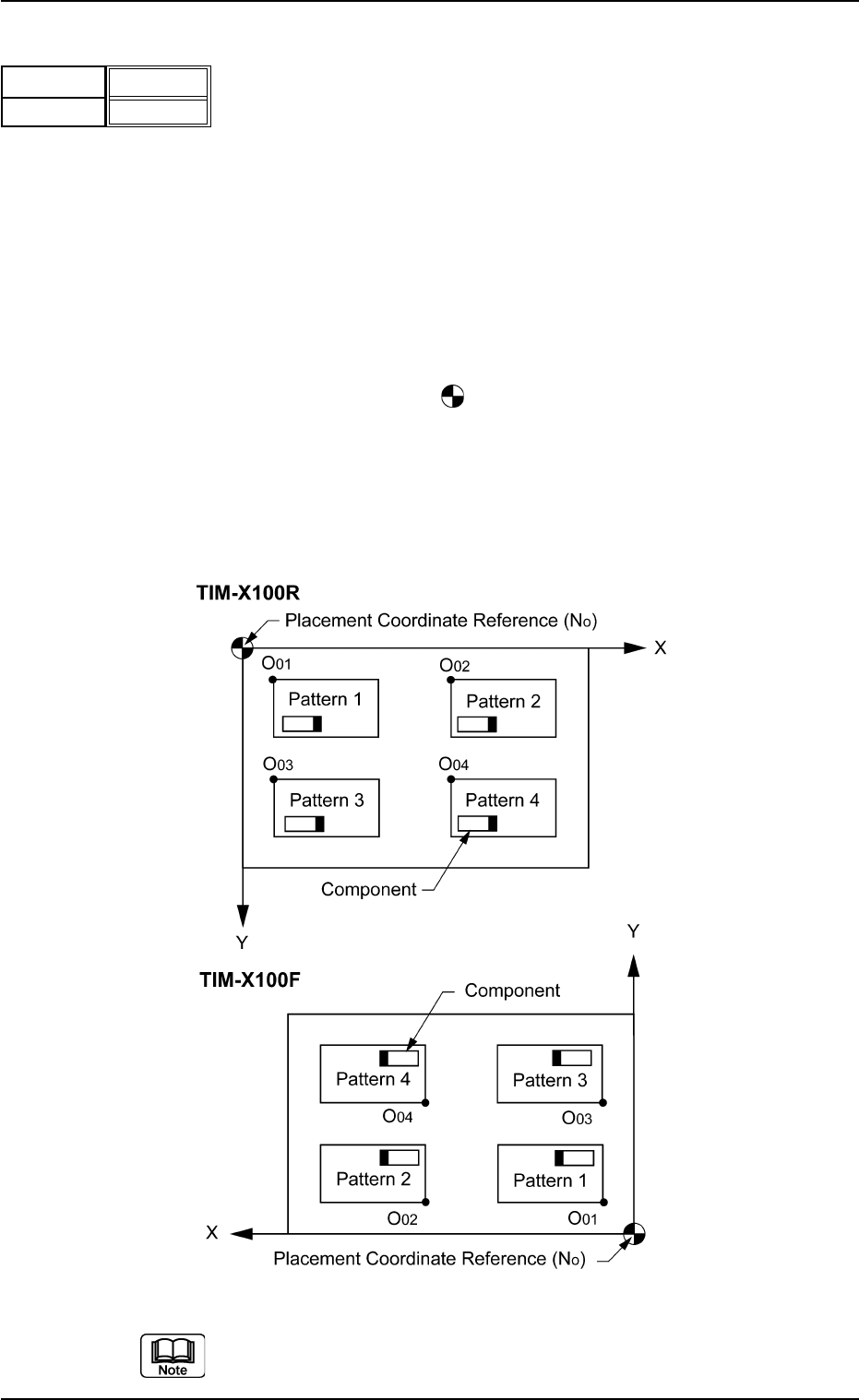
Set the coordinates of each pattern origin (O
01
through O
n
)
based on the placement coordinate reference point (N
0
).
Unit: mm
A pattern origin refers to the reference coordinates of a re-
petitive pattern.
The pattern origins (reference coordinates) must be deter-
mined, regarding the "Z-theta" data as "0°" (described in
"(C03_03)" and located at corners on the same side as the
placement coordinate reference point (N
0
).
N
0
: The center of is the placement coordinate refer-
ence.
O
01
: Pattern Origin of Pattern 1
O
02
: Pattern Origin of Pattern 2
O
03
: Pattern Origin of Pattern 3
O
04
: Pattern Origin of Pattern 4
Fig. 3B120 Example of Repetitive Patterns
Do not set any coordinates in the last line (last step No.).
Keep them as "000.00".
0206-003 2-58
AHB01EDTP
2.5 Placement Data
Fig. 3B119
X [mm]
010.000
Y [mm]
010.000
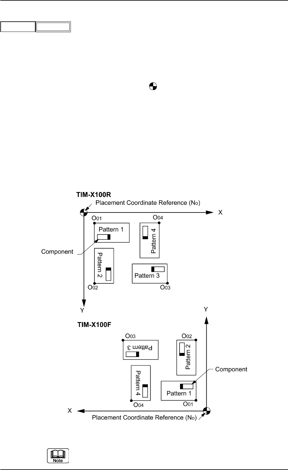
(C03_03) Z=theta
Set an angle of each pattern.
Keep the angle of the reference pattern as "000°00'".
In the figure below, "Pattern 1" is regarded as a reference
one.
Data Input Range: 0°, 90°, 180°, 270°
N
0
: The center of is the placement coordinate refer-
ence.
O
01
: Pattern Origin of Pattern 1
O
02
: Pattern Origin of Pattern 2
O
03
: Pattern Origin of Pattern 3
O
04
: Pattern Origin of Pattern 4
Pattern 1 : 0°
Pattern 2 : 90°
Pattern 3 : 180°
Pattern 4 : 270°
Fig. 3B122 Example of Repetitive Patterns
Do not set any angle in the last line (last step No.).
Keep it as "000°00'".
0206-003 2-59
AHB01EDTP
2.5 Placement Data
Z
Fig. 3B121
000°00'
(C03_04) H
The component height can be corrected.
When a parameter is set as "H" data in the last line (last step
No.), it becomes invalid because "E" is set in the "C (Control
Command)" text box.
(C03_05) C
Enter some of the following control commands.
- (hyphen): This command handles the steps as those
for component placement.
S: This command invalidates the steps specified
as those for component placement.
C: This command invalidates the steps specified
as those for component placement.
Note: As for dispensers, these steps become
valid.
D: This command handles the steps as those for
component placement.
Note: As for dispensers, these steps become
invalid.
E: When placement data (O) is not created, this
shows the end of the steps in the placement data
(P).
Confirm that "0" (zero) is set in the "X [mm]", "Y [mm]",
"Z=theta", "B-X [mm]", and "B-Y [mm]" for the last step
and set "E" in the "C".
(C03_06) Comment
Set a comment for each step No.
Up to 32 characters (alphanumerics and marks) can be
used.
The automatic operation is not affected by these comments.
2.5 Placement Data
H
Fig. 3B123
+0.00
Comment
Fig. 3B125
0308-004 2-60 AHB01EDTP
C
Fig. 3B124
-
If a control command other than the following ones is
used, the step becomes invalid.
CAUTION