3OM-1075-002.pdf - 第271页
2.1.5.2 "Stocker Mark" T ab • Sheet Layout When the "Stocker Mark" tab is pressed in the "Nozzle" tab sheet, the following tab sheet appears. Fig. 3E40 "Stocker Mark" T ab Sheet • …
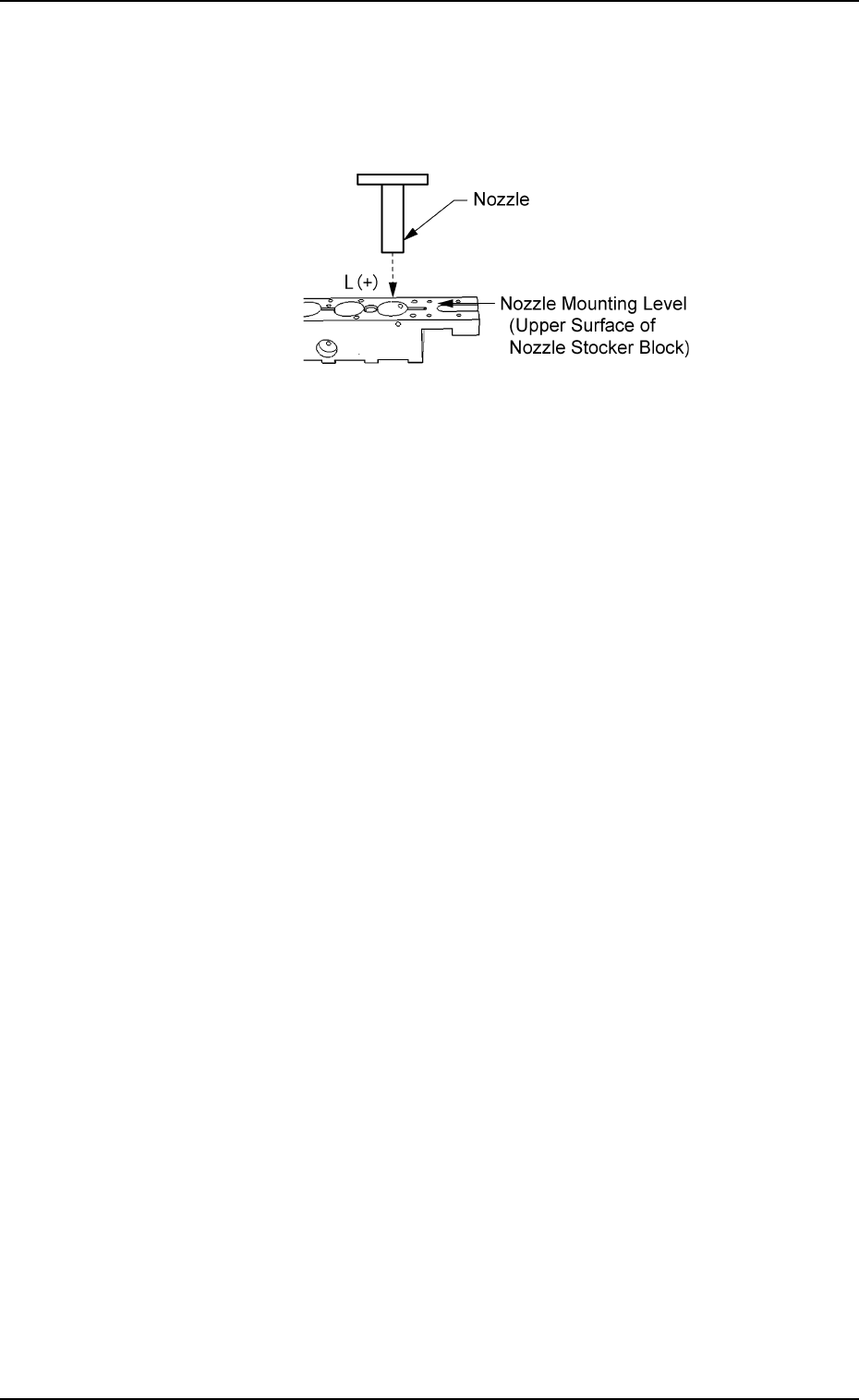
L (High) [mm]
When a value is entered with a plus (+) sign, the nozzle change
position (height) is changed in the L (+) direction (shown below),
concluding that the descending stroke has increased.
Fig. 3E39
L (Mount) [mm]
Set an offset value (offset in vertical (height) direction of the head)
required when a nozzle is attached to the head.
(This is added to the parameter in the "L (High) [mm]" text box.)
When a value is set with a plus (+) sign, the head descends, con-
cluding that the descending stroke has increased.
L (Storage) [mm]
Set an offset value (offset in vertical (height) direction of the head
required when a nozzle is stored.
(This is added to the parameter in the "L (High) [mm]" text box.)
When a value is set with a plus (+) sign, the head descends, con-
cluding that the descending stroke has increased.
2.1 "Offset Data" Tab
0206-003 5-39 AHB01EDTP
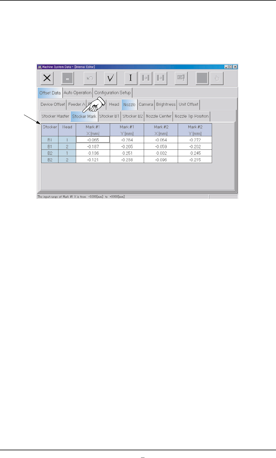
2.1.5.2 "Stocker Mark" Tab
• Sheet Layout
When the "Stocker Mark" tab is pressed in the "Nozzle" tab sheet,
the following tab sheet appears.
Fig. 3E40 "Stocker Mark" Tab Sheet
• Sheet Composition
*1 Offset Items
Set the offset values of Marks #1 and #2 on Heads #1 and #2 for
each stocker (B1 and B2).
X [mm] (Horizontal) and Y [mm] (Vertical)
This offset data is used to adjust the positional deviations compared
with the design dimensions of the nozzle stocker unit positions
(viewed from the P.C.B. positioning reference X/Y coordinates (PL-
XY Coordinates: Origin P0)). The value based on the PL-XY coordi-
nate system must be entered in each text box.
The positional deviations based on the design values are calculated
through recognition operations on Marks #1 and #2 on the upper
surface of the nozzle stocker base.
0308-004 5-40
AHB01EDTP
2.1 "Offset Data" Tab
*1
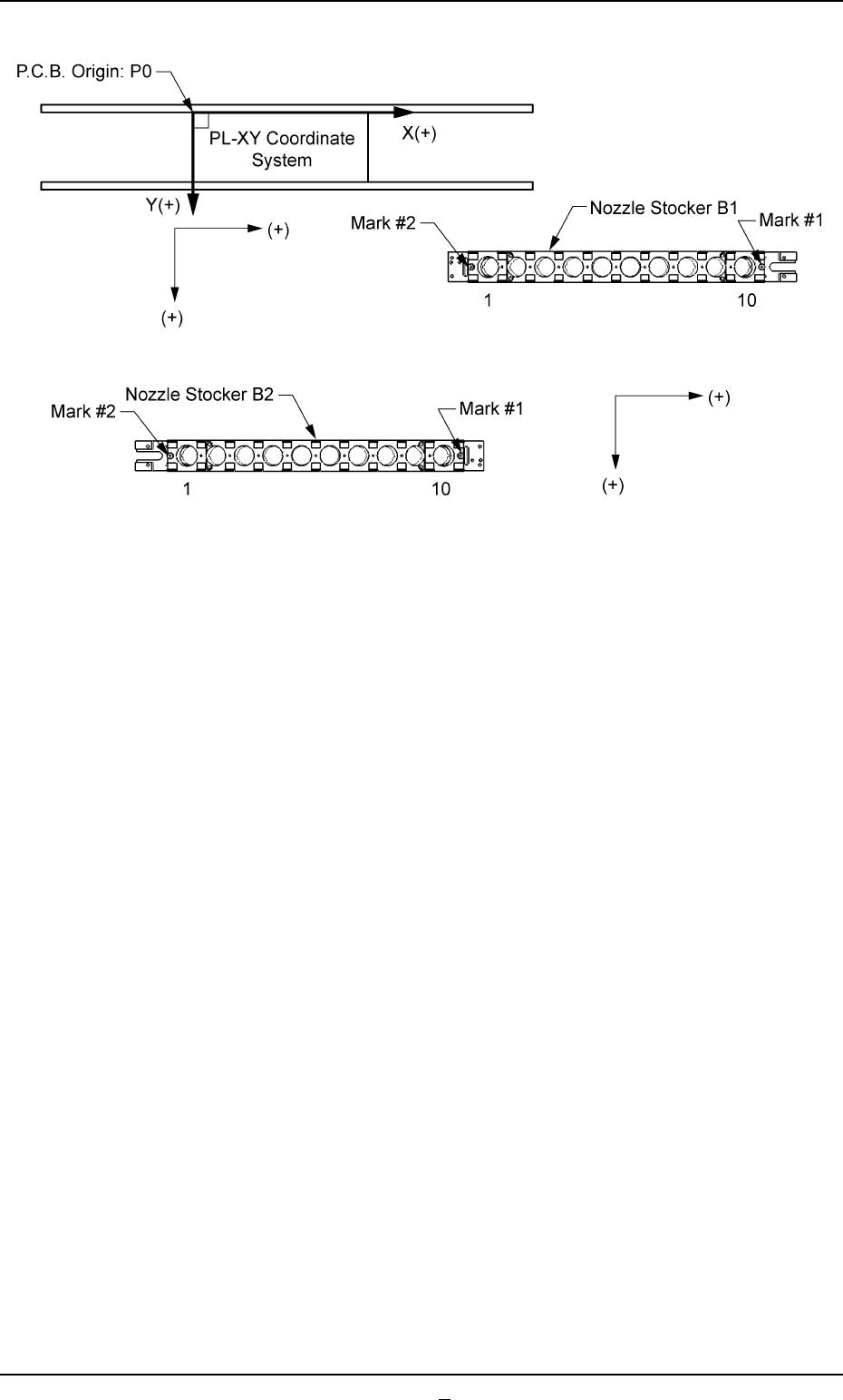
Fig. 3E41
0206-001 5-40-1
AHB01EDTP
2.1 "Offset Data" Tab