3OM-1075-002.pdf - 第70页
(C02_05) Z=theta Set angles for component placement. Data Input Range: 0°00 ′ to 359°59 ′ The placement angles must be determined according to the packaged posture of components on the tape feeder or the multi-layer tray…
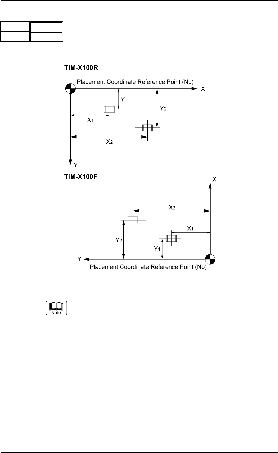
(C02_04) X [mm], Y [mm]
Set Coordinates X and Y for component placement.
The coordinates must be based on the placement coordi-
nate reference point (N
0
).
Unit: mm
Fig. 3B101
Do not set any coordinates for component placement in the last
line (last step No.).
Keep them as "000.00".
0206-002 2-50
AHB01EDTP
2.5 Placement Data
X [mm]
Fig. 3B100
Y [mm]
010.00
010.00
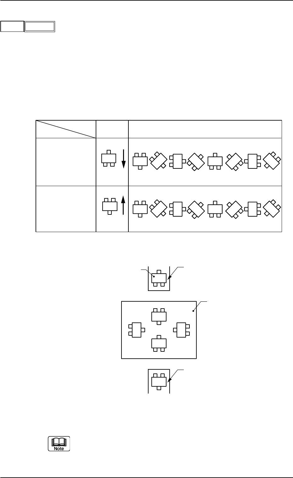
(C02_05) Z=theta
Set angles for component placement.
Data Input Range: 0°00′ to 359°59′
The placement angles must be determined according to the
packaged posture of components on the tape feeder or the
multi-layer tray feeder (option).
Example:
Fig. 3B103
Do not set any angle for component placement in the last line
(last P-No.).
Keep it as "000°00′".
Z
(Angle)
0° 45° 90° 135° 180° 225° 270° 315°
0°
270°
180°
90°
Feeder Base #1
and Multi-Layer
Tray Feeder
(Option)
Packaged
Posture
User Direction
of Tape Feed
Feeder Bases #3
and #4
Packaged
Posture
User Direction
of Tape Feed
Rear View of Machine
Packaged Posture of Component on Feeder
Tape Feeder
Multi-Layer Tray Feeder (Option)
P. C. B .
Front View of Machine
Tape Feeder
0206-003 2-51 AHB01EDTP
2.5 Placement Data
045°00′
Z
Fig. 3B102
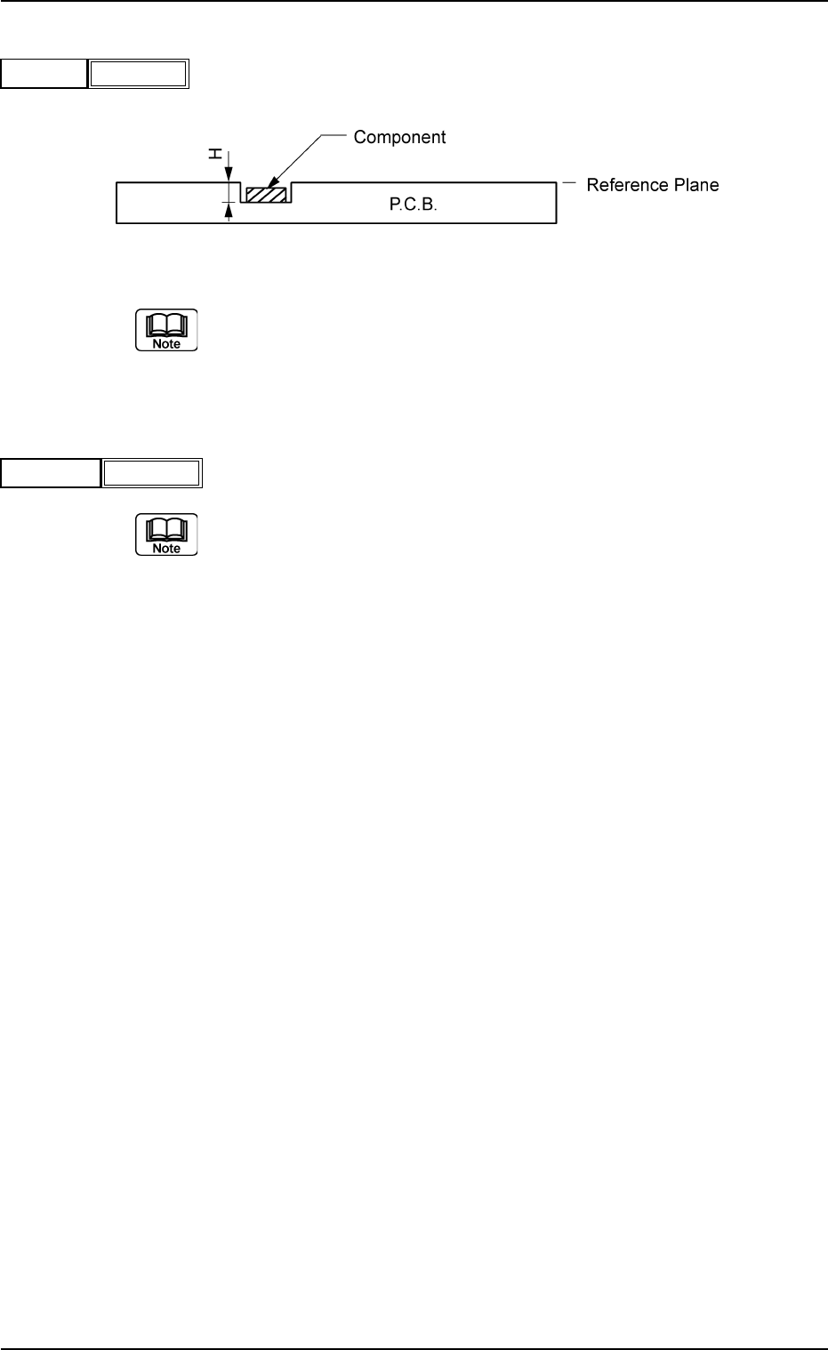
(C02_06) H [mm]
The component placement height can be corrected.
Fig. 3B105
When a parameter is set as "H" data in the last line (last step
No.), it becomes invalid because "E" is set in the "C (Control
Command)" text box.
(C02_07) Fdr. No.
Set the Nos. of the feeders loaded with components.
(a) The feeder Nos. (Fdr. Nos.) to be set here must be speci-
fied in the placement feeder location data.
(b) Do not set any feeder No. in the last line (last step No.).
Keep it as "000".
Fig. 3B106
0206-002 2-52 AHB01EDTP
2.5 Placement Data
H [mm]
Fig. 3B104
+0.00
Fdr. No.
101