3OM-1075-002.pdf - 第237页
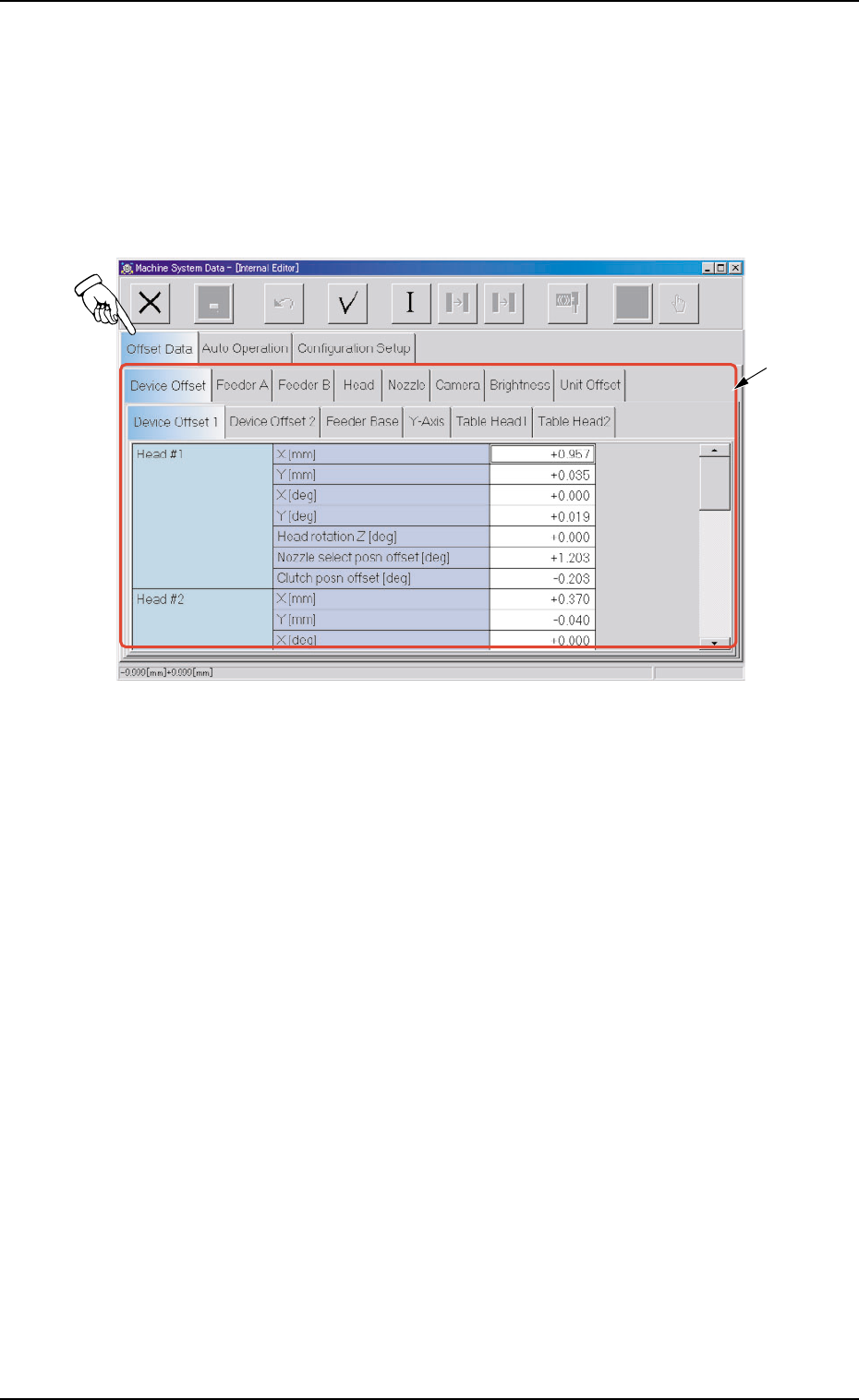
2 . 1 "Offset Data" T ab • • • • • Sheet Layout When the "Offset Data" tab is pressed in the "Machine System Data" window , the following tab sheet appears. Fig. 3E4 "Offset Data" …
*2 Icons
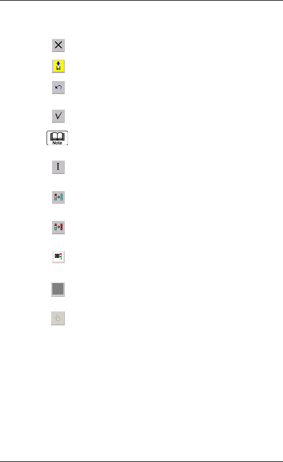
The following functions can be executed.
: When pressed, this closes the "System" window.
: When pressed, this saves the edited contents.
: When pressed, this reverses the effect of your previous
action.
: When pressed, this checks the entered parameters.
When an error is found, an error message box opens.
: When pressed, this resumes the defaults in the selected
range.
: When pressed, this fills all the selected text boxes with
the parameter in the first text box.
: When pressed, this fills all the selected text boxes with
the parameter in the last text box.
: When pressed, this changes the parameters in the "Con-
figuration Setup" tab sheet to the standard ones.
: When the "Feeder B" tab sheet is active and this button
is pressed, all offset data is cleared.
: When pressed, this displays a list of component IDs,
making it possible to select a component ID.
0308-003 5-5
AHB01EDTP
2. "Machine System Data" Window
2.1 "Offset Data" Tab
••
••
• Sheet Layout
When the "Offset Data" tab is pressed in the "Machine System Data"
window, the following tab sheet appears.
Fig. 3E4 "Offset Data" Tab Sheet
0308-003 5-6
AHB01EDTP
2.1 "Offset Data" Tab
*1

0206-003 5-7 AHB01EDTP
2.1 "Offset Data" Tab
••
••
• Sheet Composition
*1 Tabs and Tab Sheets
The "Offset Data" tab sheet is provided with the following 8 tab
sheets. When a tab is pressed, the corresponding tab sheet ap-
pears.
Table 3E2
Tabs Description
Device Offset The corresponding tab sheet enables the operator to adjust the posi-
tional and angular deviations based on the design dimensions repre-
senting the X/Y beam driving X/Y coordinates viewed from the P.C.B.
positioning X/Y coordinates.
Feeder A This offset data is used independently for the machine. The corre-
sponding tab sheet enables the operator to adjust the positional de-
viation compared with the design dimensions representing the com-
ponent pick-up position and height of the feeder for each individual
feeder slot Nos. (Fdr. No.) viewed from the P.C.B. positioning X/Y co-
ordinates.
Feeder B The corresponding tab sheet enables the operator to correct the varia-
tions, etc., for each individual feeders.
Head The corresponding tab sheet enables the operator to correct the posi-
tional deviation (placement coordinates) caused due to the deviation
of straightness (skew) of each individual head up/down axis guides
and set up the offset data for the distance between the scanning co-
ordinate center of the P.E.C. camera and the head rotational center.
Nozzle The corresponding tab sheet enables the operator to adjust the posi-
tion of the nozzle stocker unit based on the P.C.B. positioning refer-
ence.
Camera The corresponding tab sheet enables the operator to adjust the posi-
tion of the component recognition movable and fixed cameras, the
gain and level for component recognition magnification, and the hori-
zontal swing of the P.E.C. recognition camera.
Brightness The corresponding tab sheet enables the operator to set the bright-
ness of the lighting units for component and P.C.B. recognition opera-
tions and offset teaching operation.
Unit Offset The corresponding tab sheet enables the operator to adjust the posi-
tion of the component storage box.