3OM-1075-002.pdf - 第56页
2 . 4 Placement Feeder Location Data (B01) Feeder Base #1, #3, #4 It can be determined which components must be used and which feeder base (Fdr . No.) must be loaded with the se- lected components. The feeder bases can b…
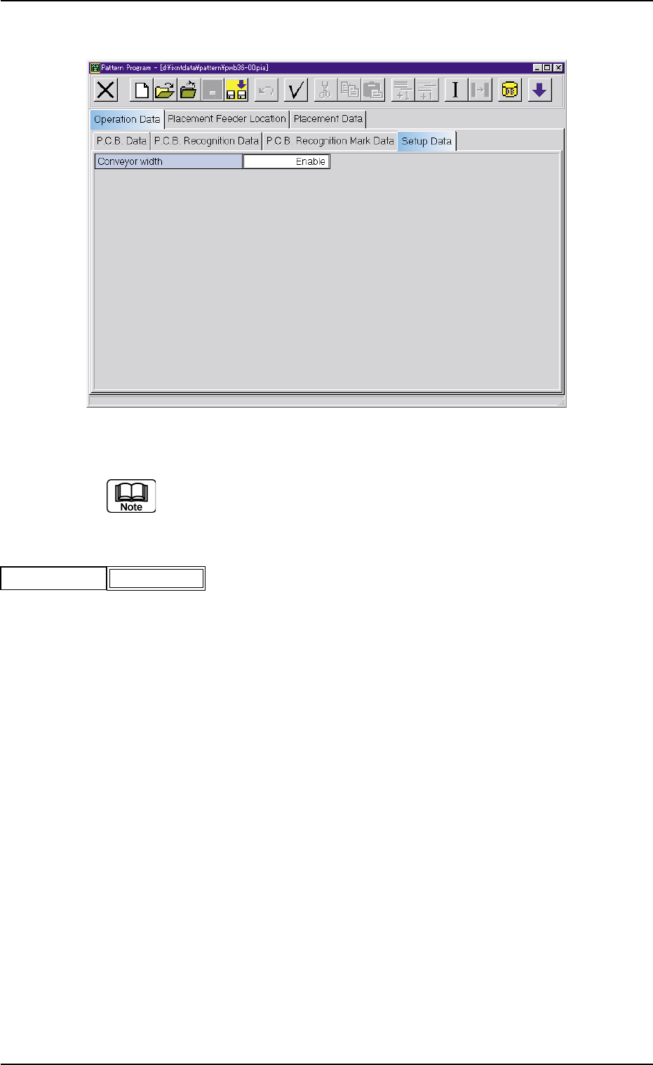
(A04) Setup Data
Fig. 3B61 Edit Window (Example)
Unless "Enable" is selected for a device to be set up, the ma-
chine does not perform any setup operation on the device.
(A04_01) Conveyor width
Set "Disable" or "Enable" in the text box.
0206-002 2-36 AHB01EDTP
2.3 Operation Data
Conveyor width
Fig. 3B62
Enable
2.4 Placement Feeder Location Data
(B01) Feeder Base #1, #3, #4
It can be determined which components must be used and
which feeder base (Fdr. No.) must be loaded with the se-
lected components.
The feeder bases can be loaded with tape and vibratory stick
feeders.
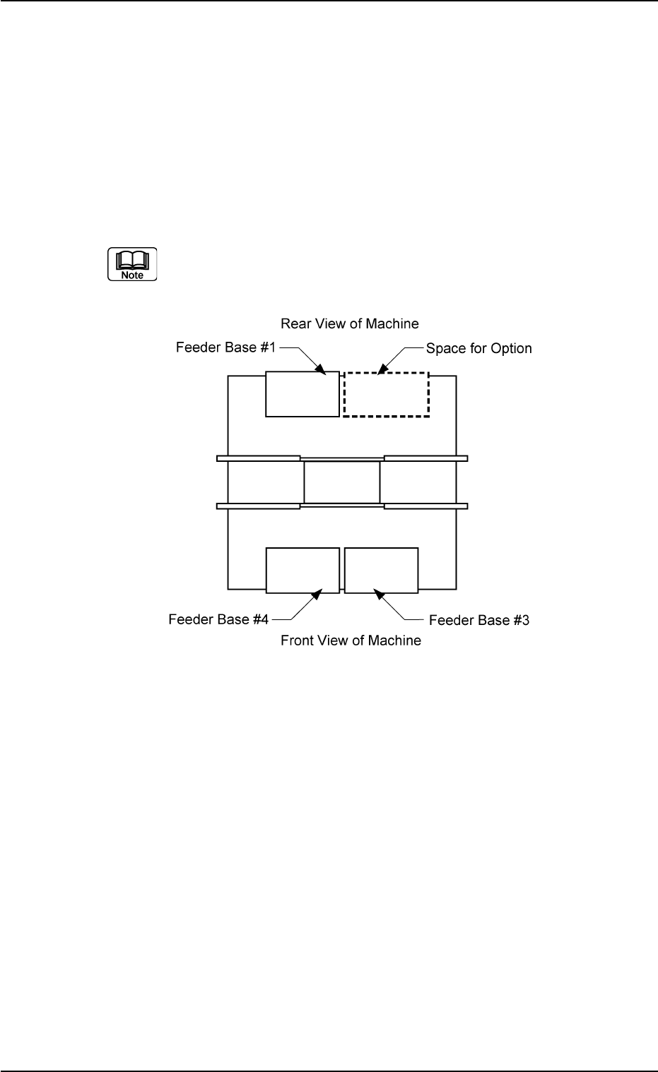
(a) The following shows the positional relation between the
feeder bases.
Fig. 3B63
(b) The multi-layer tray feeder (option) or Feeder Base #2 (op-
tion) can be installed in the option space.
Check which option is installed and then create the data.
(c) Refer to the instruction manual of the multi-layer tray feeder
for the placement feeder location data of the multi-layer
tray feeder (option).
(d) Refer to the instruction manual of Feeder Base #2 (Op-
tion) for the placement feeder location data of Feeder Base
#2.
0206-002 2-37 AHB01EDTP
2.4 Placement Feeder Location Data
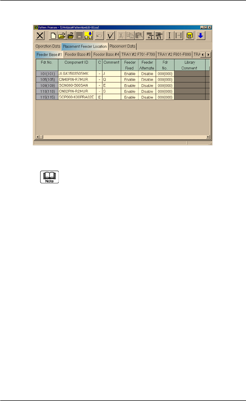
Fig. 3B64 Edit Window (Provided with Multi-Layer Tray Feeder 2)
The "TRAY #2 F701-F799", "TRAY #2 F801-F899", and "TRAY
#2 STEP" tabs are provided for the options.
The tab sheet may look different, depending on which options
are selected.
2.4 Placement Feeder Location Data
0308-003 2-38 AHB01EDTP