3OM-1075-002.pdf - 第312页
Output mode Select "Standard", "Interval", or "SMEMA" to determine how to transfer a P .C.B. from the main machine to the output machine. Standard When the output machine is manufactured by …

Y clamp timer [sec]
Set a period of time during which the Y pusher moves forward or
backward for P.C.B. alignment in Y direction (horizontal P.C.B. posi-
tioning). The set parameter is used commonly for both forward and
backward movements.
The Y pusher is not provided with any sensors for detection of the
forward or backward movement because the P.C.B. locating side
clamp (Y pusher) moves only a short distance. Therefore, the timing
of movement is controlled by the software-based timer.
••
••
• Default: 0.3 seconds
••
••
• Enter a period of time during which the Y alignment is made com-
pletely.
••
••
• This is used for the switchover timing (Clamp ON or OFF) of the
application (software).
••
••
• Whenever the speed of the forward or the backward movement is
adjusted, it is required to change the set parameter to avoid any
impact which may be given to a P.C.B. during Y alignment.
••
••
• Data Input Range: 0 to 99 seconds
When the parameter is too large, excessively long time will
be required for P.C.B. positioning or releasing.
Z clamp timer [sec]
Set the time of the P.C.B. clamp timer in the text box.
This is used for the switchover timing (Clamp ON or OFF) of the
application (software).
Conveyor buffer setup
Determine whether or not the P.C.B.’s should be buffered on the po-
sitioning conveyor.
Set "Enable" or "Disable" in the text box.
The set parameter becomes effective when "Priority P.C.B. Flow" is
set in the "Locate mode" text box and the P.C.B. size is less than 150
mm.
P.C.B. detection off delay time [sec]
Set the P.C.B. detection delay time for reverse positioning.
The data input range is "0 to 0.999 seconds. "
2.2 "Auto Operation" Tab
01 12-001 5-79 AHB01EDTP
Output mode
Select "Standard", "Interval", or "SMEMA" to determine how to
transfer a P.C.B. from the main machine to the output machine.
Standard
When the output machine is manufactured by us, set "Standard"
in the text box.
When the work request signal is received from the output ma-
chine, the P.C.B. transfer signal of the machine is turned ON and
a P.C.B. is transferred to the output machine by the output con-
veyor.
When the work request signal is not turned OFF within the speci-
fied time after a P.C.B. unloading action has started, the machine
stops in an error condition.
Interval
When the work request signal of the output machine is turned
ON, P.C.B.’s on the machine side are transferred to the output
machine.
The conveyor stops when the output conveyor timer has reached
the specified time.
The machine starts its unloading actions when the unloading con-
dition is fulfilled after the conveyor has stopped running and the
time specified in the "Output interval timer [sec]" text box has
elapsed.
No error detection is made.
SMEMA
P.C.B.’s are transferred according to the "SMEMA" standard.
Output interval timer [sec]
When "Interval" is set in the "Output mode" text box, set the time
as interval time for P.C.B. unloading actions.
The data input range is "0 to 99 seconds".
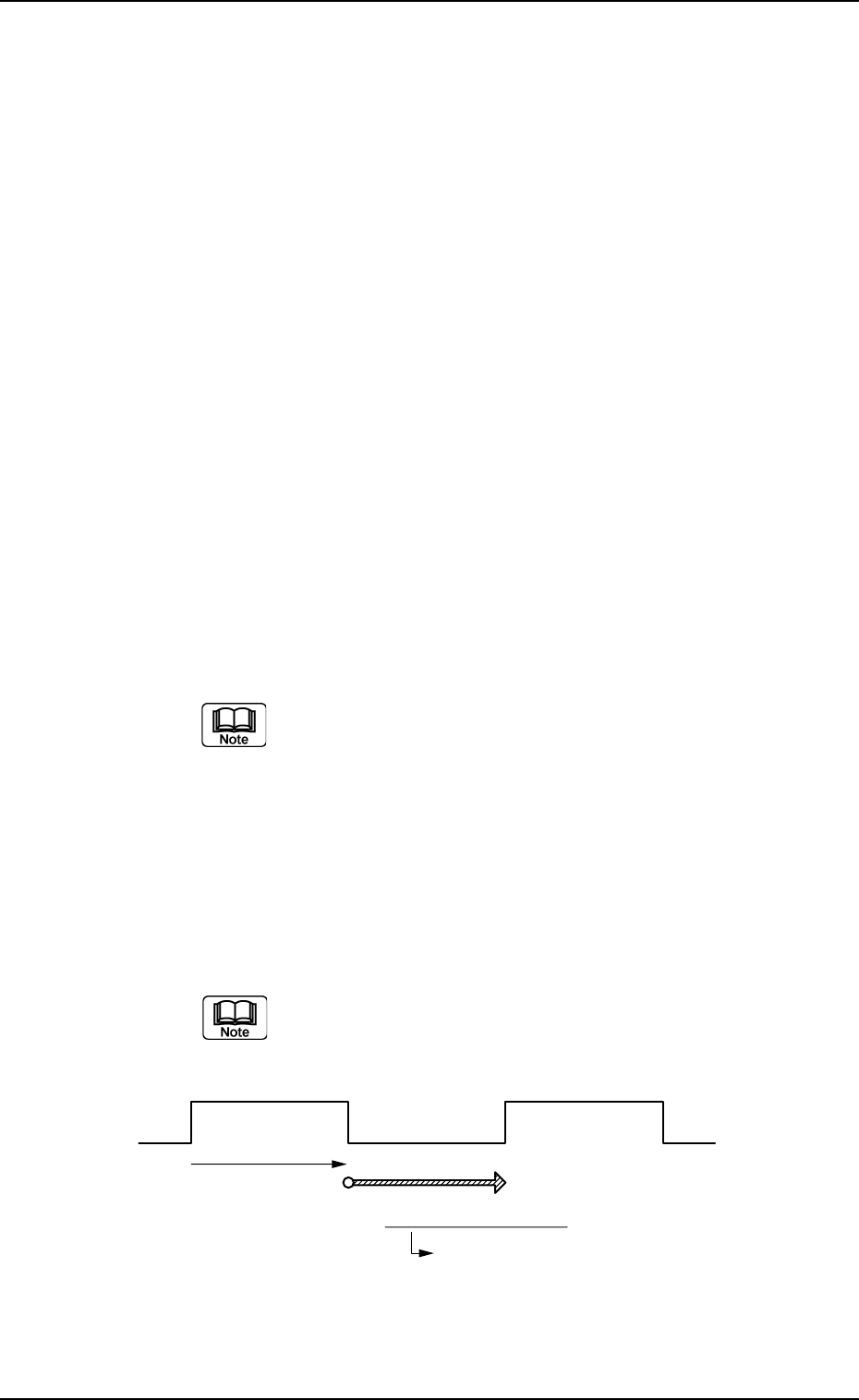
Fig. 3E73
2.2 "Auto Operation" Tab
Output Conveyor ON Unloading of Subsequent P.C.B.
Controlled by Output
Conveyor Timer #1
Output Interval Timer
This timer gives an interval
time until the subsequent P.C.B.
is unloaded.
0206-002 5-80 AHB01EDTP

0206-002 5-81 AHB01EDTP
2.2 "Auto Operation" Tab
Output conveyor Timer
Timer #1 [sec], Timer #2 [sec], and Buffer setup
Set the time to limit the operating time (P.C.B. reception by the
output machine) of the output conveyor.
(a) Add 2 seconds (approx.) to the time required for
P.C.B. reception by the output machine and set the
time in the text box.
(b) The data input range is "0 to 99 seconds".
Timer #2 [sec]
Set the time to limit the operating time of the output conveyor to
transfer a P.C.B. on the main machine side.
The data input range is "0 to 99 seconds".
Buffer setup
Determine whether or not the P.C.B.’s should be buffered on the
output conveyor.
Set "Enable" or "Disable" in the text box.
Simultaneous transfer setup
Determine whether or not the P.C.B. on the input conveyor should
be transferred to the positioning conveyor and the P.C.B. on the
positioning conveyor to the output conveyor at the same time.
Set "Enable" or "Disable" in the text box.
P.C.B. transfer direction
Set a P.C.B. transfer direction in the text box.
"L Æ R"
The P.C.B. flows from the left to the right.
"R Æ L"
The P.C.B. flows from the right to the left.
When the setting is changed, it is required to perform
the zeroing operation again.