3OM-1075-002.pdf - 第38页
(A01_06) Placement mode (Not Available) Set "Placement" or "Pass" in the text box. In normal cases, select "Placement". When "Pass" is set in this text box and the pattern program …
Upper Pass Line:
This line is the lowest level for the X/Y beam movement
when the thickness of a previously-placed component
(already-placed component) is more than 6.5 mm. (Only
in the P.C.B. area)
The maximum thickness of the placed component is man-
aged on the machine side to automatically change the
component transfer level every time a component is
placed, avoiding any interference between the picked and
placed components.
(c) When components are placed previously and the main ma-
chine is operated with "0.00" (zero) in this text box, some
of the previously-placed components may interfere with
components to be placed newly.
(d) It is advisable that placement data should be created such
that shorter components are placed before the tallest one.
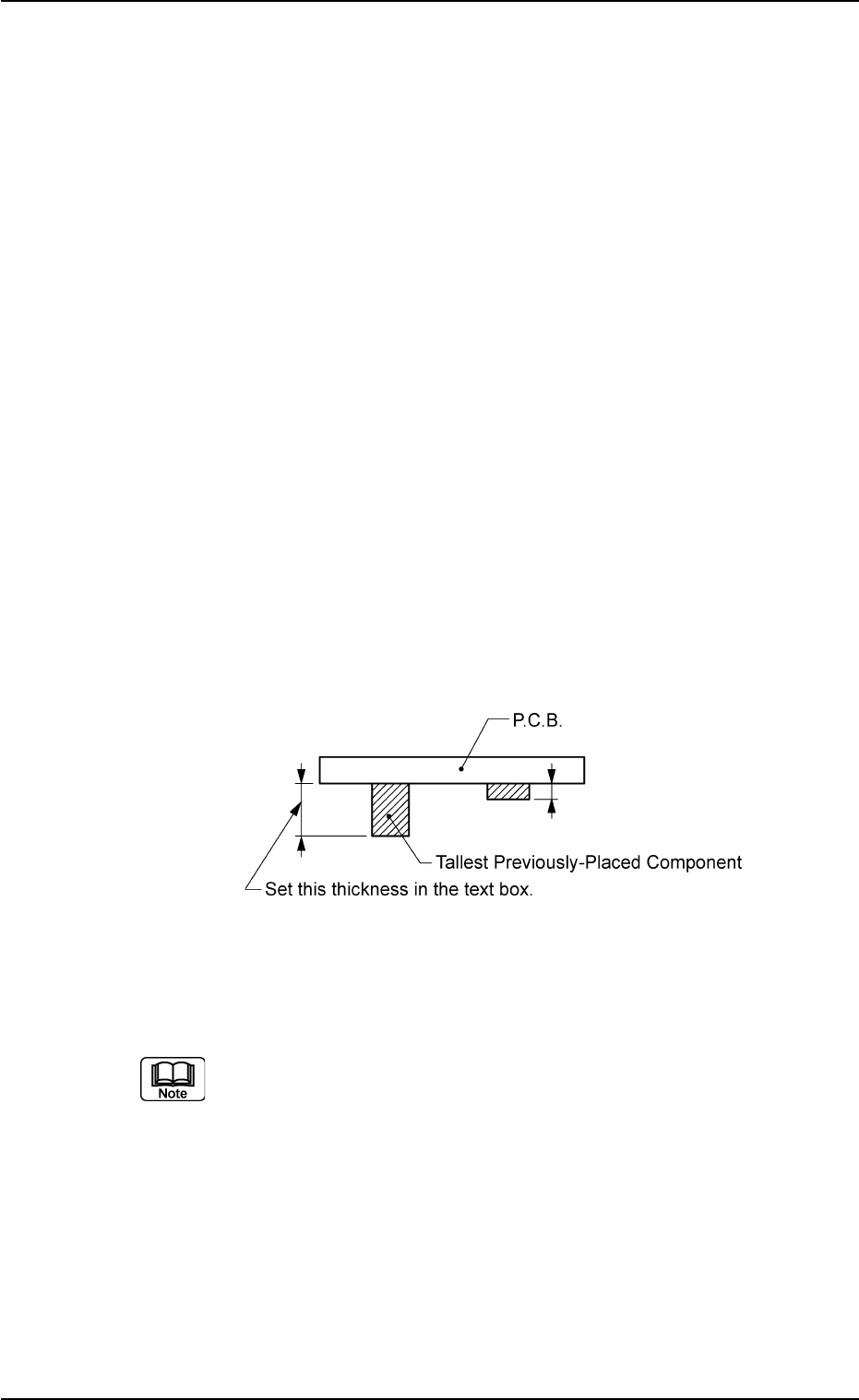
P.C.B. bottom [mm]
When P.C.B.’s with some components already mounted on
the lower surfaces (back) by the input machine are trans-
ferred to this machine, be sure to enter the thickness of the
highest component in the text box.
Unit: mm
Fig. 3B22
Data Input Range: 0 to 30.00
(a) The set parameter is used to determine the position (el-
evation) of the first backup table when the P.C.B. is trans-
ferred to the P.C.B. positioning section.
(b) When P.C.B.’s have previously-placed components and
"0" (no previously-placed components) is set in the text
box, the support pins may interfere with the previously-
placed components while the P.C.B. is being transferred
to the P.C.B. positioning section.
0206-003 2-18 AHB01EDTP
2.3 Operation Data

(A01_06) Placement mode (Not Available)
Set "Placement" or "Pass" in the text box.
In normal cases, select "Placement".
When "Pass" is set in this text box and the pattern program
data is selected as current one, the vacuum pump motor is
automatically turned off.
0206-002 2-19
AHB01EDTP
2.3 Operation Data
Placement mode
Fig. 3B23
Placement
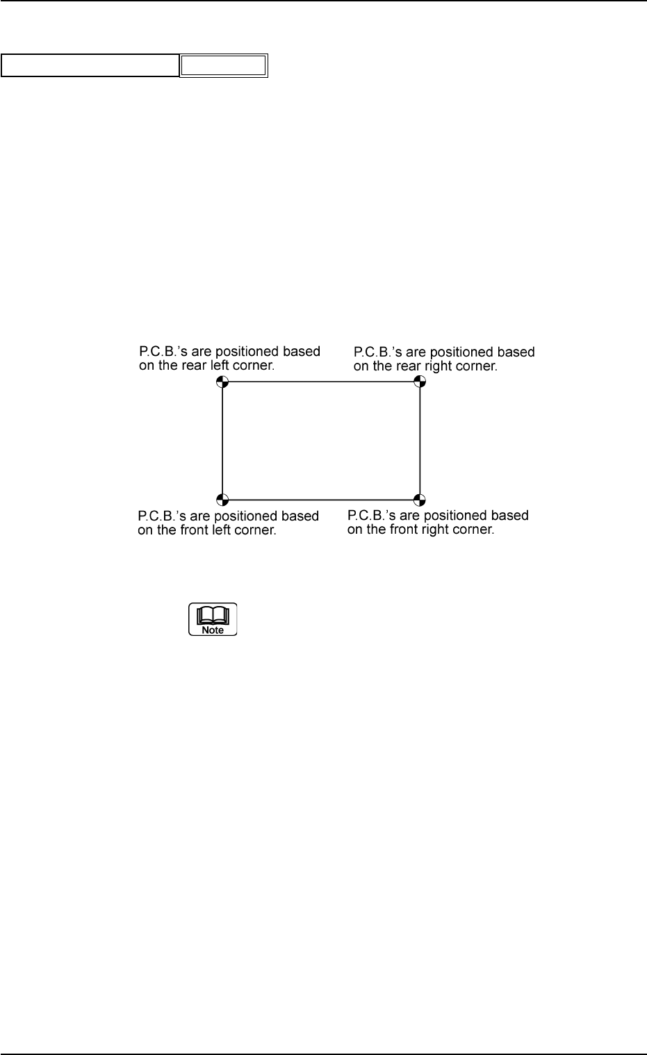
(A01_07) P.C.B. positioning reference
Displayed is a P.C.B. positioning reference point.
Rear Left : P.C.B.’s are positioned based on the rear left
corner.
Front Left : P.C.B.’s are positioned based on the front left
corner.
Front Right : P.C.B.’s are positioned based on the front
right corner.
Rear Right : P.C.B.’s are positioned based on the rear right
corner.
Fig. 3B25
(a) TIM-X100R is based on "Rear Left" or "Rear
Right".
TIM-X100F is based on "Front Left" or "Front
Right".
(b) The P.C.B. positioning reference must be
changed when the pattern program (prepared
for the machine that requires a different P.C.B.
positioning reference) is used.
0206-003 2-20 AHB01EDTP
2.3 Operation Data
P.C.B. positioning reference
Fig. 3B24
Rear Left