3OM-1075-002.pdf - 第228页
01 12-001 4-45 AHB01EDTP (4) [C: vacuum sensor] Button Each text box shows the total number of component pick-up er- rors detected by the vacuum sensor (errors not detected through the recognition operation) for each ind…
0206-002 4-44 AHB01EDTP
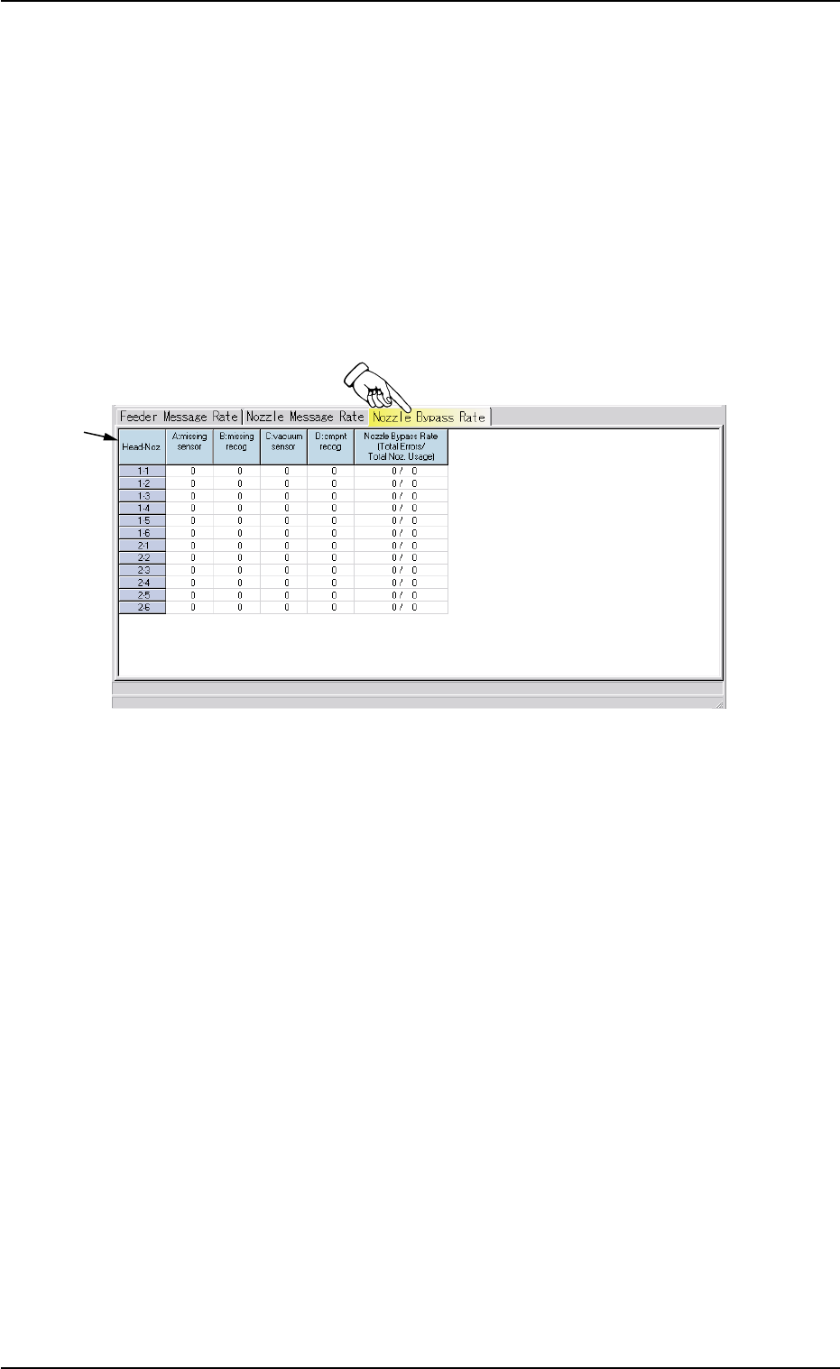
5.3 "Nozzle Bypass Rate" Tab
The corresponding tab sheet displays the pick-up rates (managed for
each individual nozzles) based on the nozzle bypass rates specified in
the auto operation setup data.
• Sheet Layout
When the "Nozzle Bypass Rate" tab is pressed in the "Bypass &
Rate Data" window, the following tab sheet appears inside the win-
dow.
Fig. 3D23 "Nozzle Bypass Rate" Tab Sheet
• Sheet Composition
*1 Items
The following items are displayed.
(1) [Head-Noz.] Button
Shown are the nozzle Nos. (1 through 6) on each head No. (1 and
2).
(2) [A: missing sensor] Button
Each text box shows the number of missing components de-
tected by the vacuum sensor.
(3) [B: missing recog] Button
Each text box shows the number of missing components de-
tected through recognition processing.
5.3 "Nozzle Bypass Rate" Tab
*1

01 12-001 4-45 AHB01EDTP
(4) [C: vacuum sensor] Button
Each text box shows the total number of component pick-up er-
rors detected by the vacuum sensor (errors not detected through
the recognition operation) for each individual feeders.
(5) [D: cmpnt recog] Button
Each text box shows the number of component recognition er-
rors.
(6) [Nozzle Bypass Rate (Total Errors/Total Noz. Usage)] Button
Each text box shows the rate of pick-up errors (the number of
pick-up errors per number of picks) for each individual nozzles.
5.3 "Nozzle Bypass Rate" Tab

0308-001 4-46 AHB01EDTP