3OM-1075-002.pdf - 第127页
0308-002 2-107 AHB01EDTP 4.3 "Placement Feeder Location" T ab (4) Make appear the vibratory feeder tab that corresponds to the refer- ence feeder No. (Fdr . No.). (5) Allocate the carrier stick components for t…
0206-001 2-106 AHB01EDTP
4.3 "Placement Feeder Location" Tab
Fig. 3B173
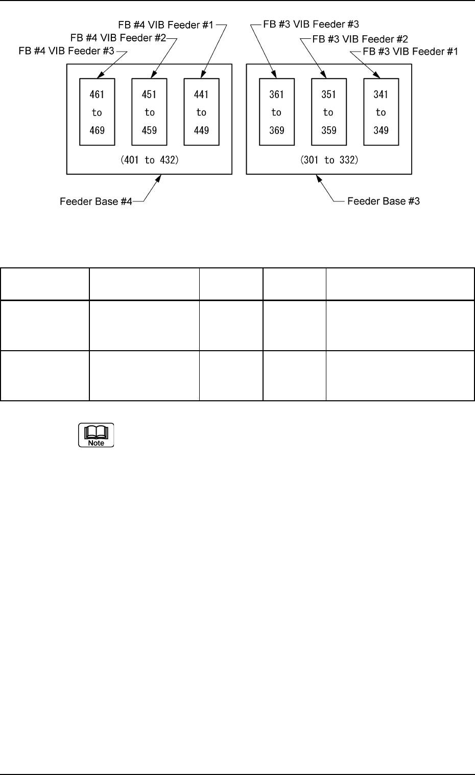
Table 3B35
Feeder Base No. Unit No. Reference Exclusive Carrier Stick Fdr. No.
Fdr. No. Fdr. No.
FB #3 VIB Feeder #1 303 301 to 310 341 to 349
Feeder Base #3 FB #3 VIB Feeder #2 315 311 to 322 351 to 359
FB #3 VIB Feeder #3 327 323 to 332 361 to 369
FB #4 VIB Feeder #1 403 401 to 410 441 to 449
Feeder Base #4 FB #4 VIB Feeder #2 415 411 to 422 451 to 459
FB #4 VIB Feeder #3 427 423 to 432 461 to 469
(a) The reference feeder Nos. (Fdr. No.) are automatically allo-
cated when the vibratory stick feeders are specified.
(b) The exclusive feeder Nos. (Fdr. Nos.) indicate the ranges
occupied exclusively on the feeder base.
No tape feeder can be allocated to this feeder No. (Fdr. No.).
0308-002 2-107 AHB01EDTP
4.3 "Placement Feeder Location" Tab
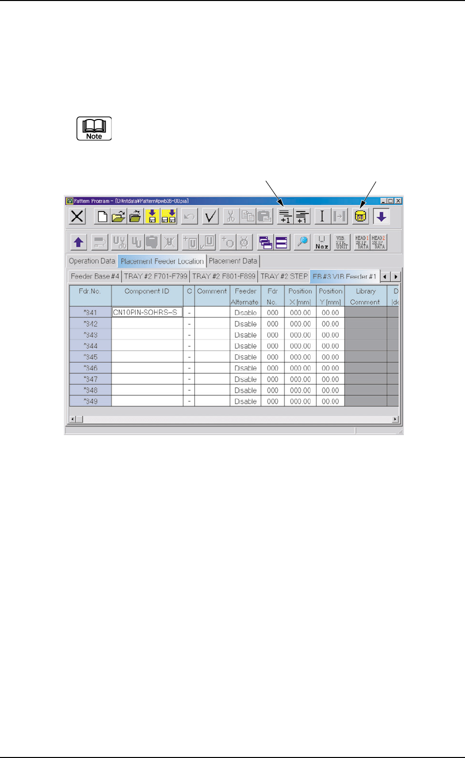
(4) Make appear the vibratory feeder tab that corresponds to the refer-
ence feeder No. (Fdr. No.).
(5) Allocate the carrier stick components for the vibratory stick feeder.
Add an Fdr. No. with the [Add One Line] icon and allocate a compo-
nent with the [Component ID List] icon.
Select a component whose carrier type is "Vibratory Stick".
Up to 9 carrier sticks can be allocated to one vibratory stick
feeder.
Fig. 3B174
(6) Set parameters in the "Position X [mm]" and "Position Y [mm]" text
boxes.
Measure the distance between the reference position of the vibra-
tory stick feeder unit and the pick-up position and enter the values in
the text boxes.
(7) Check the component library data of the allocated component.
Confirm that correct direction, carrier type, width, and nozzle are
specified.
[Add One Line] Icon
[Component ID List] Icon
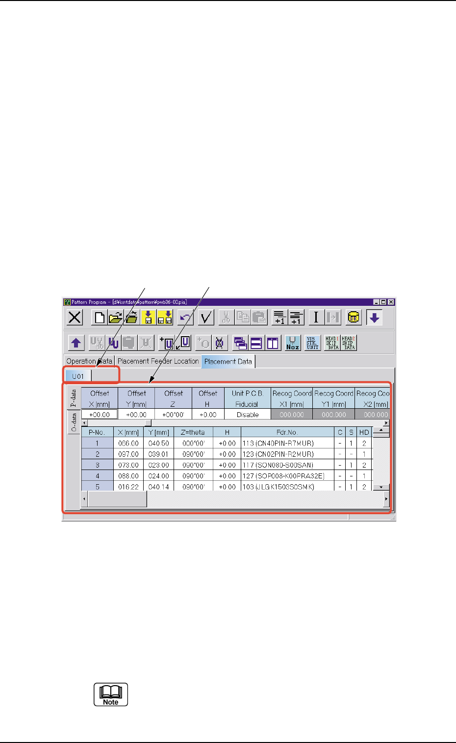
4.4 "Placement Data" Tab
The "Placement Data" tab is provided with additional "U01" to "Un" tabs,
the "P-data" tabs, and the "O-data" tabs. When each tab is selected, the
corresponding tab sheet appears.
4.4.1 "U01" to "Un" Tabs
"U01" represents "Unit No. 01" and "n" in "Un" can be any number (01,
02, 03, ...). When the "Un" tab is pressed, the corresponding tab sheet
appears, enabling you to edit the parameters.
• Sheet Layout
When the "U01" tab is pressed after the "Placement Data" tab is
selected, the following tab sheet appears.
Fig. 3B175 "U01" Tab Sheet
• Sheet Composition
Each parameter is displayed or can be entered.
*1 "U01" to "Un" Tabs
These tabs are used to select a unit. When a tab is pressed, the
corresponding tab sheet appears and is related to the selected unit.
Refer to "• Operation Procedure" described later for the de-
tailed information on how to add or delete a unit.
0206-001 2-108
AHB01EDTP
4.4 "Placement Data" Tab
*1
*2