3OM-1075-002.pdf - 第241页
Fig. 3E7 Head Origin H0 is the scanning coordinate center of P .E.C. Camera #1 installed on the head when the beam X/Y axis is located at its origin. (Head Origin: P .E.C. Camera Center) This offset data is automatically…
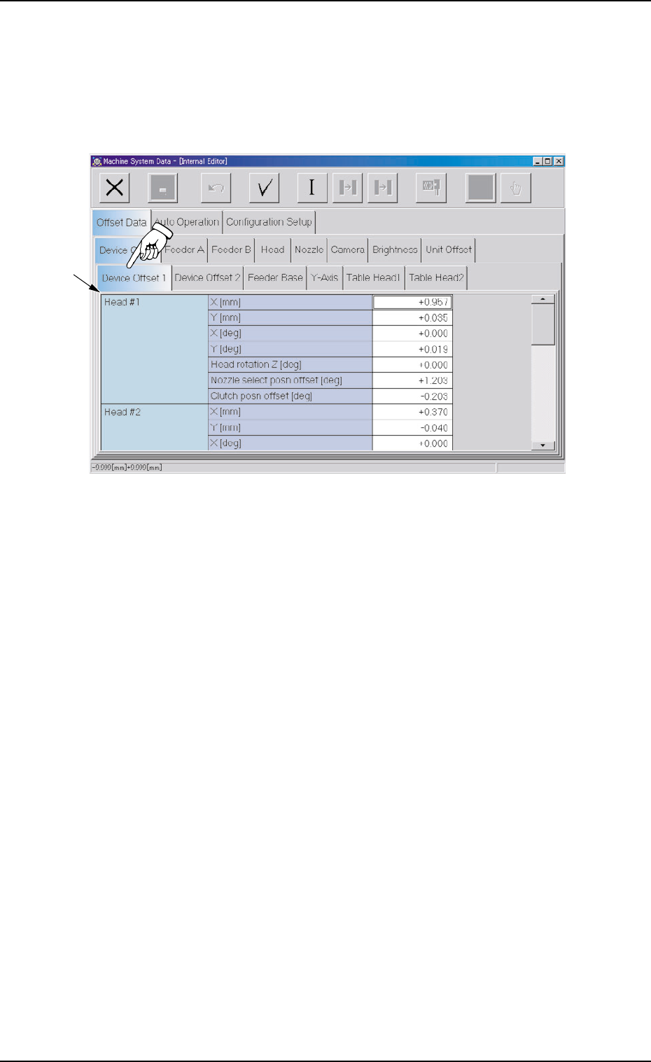
2.1.1.1 "Device Offset 1" Tab
• Sheet Layout
When the "Device Offset 1" tab is pressed in the "Device Offset" tab
sheet, the following tab sheet appears.
Fig. 3E6 "Device Offset 1" Tab Sheet
• Sheet Composition
*1 Offset Items
Set the following offset values.
Head #1 (X mm (Horizontal), Y mm (Vertical), X [deg], and Y
[deg])
The set offset parameters are used to adjust the positional and an-
gular deviations compared with the design dimensions represent-
ing the beam driving X/Y coordinates (Head Origin: H0) viewed from
the P.C.B. positioning X/Y coordinates (PL-XY: P.C.B. Origin P0).
*1
0308-004 5-9 AHB01EDTP
2.1 "Offset Data" Tab
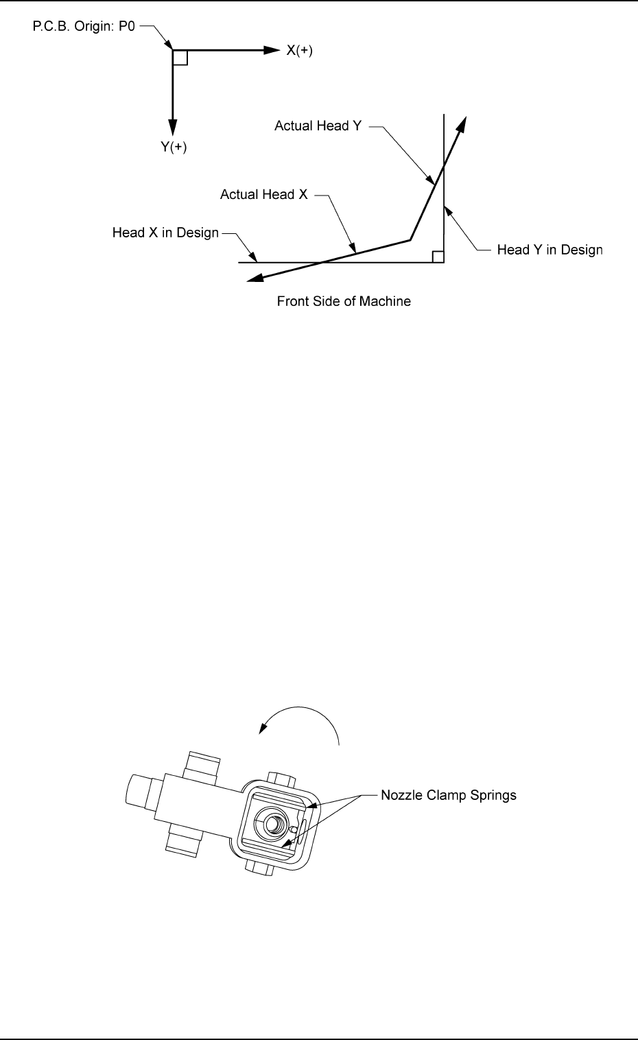
Fig. 3E7
Head Origin H0 is the scanning coordinate center of P.E.C. Camera
#1 installed on the head when the beam X/Y axis is located at its
origin.
(Head Origin: P.E.C. Camera Center)
This offset data is automatically calculated through teaching opera-
tion which is performed, using a jig P.C.B.
Head #1 (Head rotation Z [
° °
° °
° ])
This offset data (offset data for the origin position of the head rota-
tional axis) is used to adjust the directions of the nozzle clamp springs
when the nozzles must be rotated for replacement.
When the head rotational axis is zeroed and the nozzle clamp springs
face the direction shown in Fig. 3E8 (view from the bottom), a plus
parameter must be entered as the offset data.
Fig. 3E8
0206-003 5-10 AHB01EDTP
2.1 "Offset Data" Tab
2.1 "Offset Data" Tab
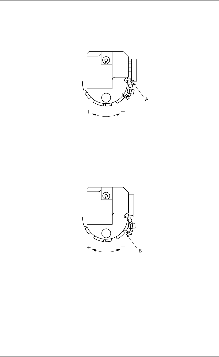
Head #1 (Nozzle select pos offset [
° °
° °
° ])
This offset data is used to adjust the position (A) where the rotor
and the nozzle lift cam can be unlocked for the selection of the nozzle
to be used on the head.
It is required to enter an angle.
Fig. 3E9
Head #1 (Clutch pos offset [
° °
° °
° ])
This offset data is used to adjust the position (B) where the rotor
and nozzle lift cam can be locked for the selection of a nozzle to be
used on the head.
It is required to enter an angle.
Fig. 3E10
0206-003 5-11 AHB01EDTP