3OM-1075-002.pdf - 第24页
1 . 4 Composition of Placement Data The set parameters are used to place the components (IDs in the place- ment feeder location data) on the points with the specified coordinates in the designated direction. One step is …

1.3 Composition of Placement Feeder Location Data
The set parameters are used to determine which feeder slot Nos. (Fdr.
Nos.) various types of components should be allocated to.
The allocated component IDs (types) must be specified for each indi-
vidual feeder bases, vibratory stick feeders and multi-layer tray feeders
(option).
When the vibratory stick feeders are used, the allocation of the vibratory
stick units and component IDs must be specified.
Refer to "2.4 Placement Feeder Location Data" in "Section 2" for de-
tails.
B01 Feeder Base #1, #3, #4 Table 3B5
Ref. No. Data Name
B01_01 Fdr. No.
B01_02 Component ID.
B01_03 C
B01_04 Comment
B01_05 Feeder Fixed
B01_06 Feeder Alternate
B01_07 Fdr. No.
B01_08 Library Comment
B01_09 Dir [deg], Carrier Data Type, Width [mm]
B01_10 Nozzle #1, C, Nozzle #2, C
TRAY #2 F701-F799, TRAY #2 F801-F899, TRAY #2 STEP (Option)
Refer to the instruction manual of the multi-layer tray feeders
(option) for details.
B02 FB #3 VIB Feeder #1, #2, #3,
FB #4 VIB Feeder #1, #2, #3
Table 3B6
Ref. No. Data Name
B02_01 Fdr. No.
B02_02 Component ID
B02_03 C
B02_04 Comment
B02_05 Feeder Alternate
B02_06 Fdr. No.
B02_07 Position X [mm], Y [mm]
B02_08 Library Comment
B02_09 Dir [deg], Carrier Data Type
B02_10 Nozzle #1, C, Nozzle #2, C
0308-004 2-4
AHB01EDTP
1.3 Composition of Placement Feeder Location Data

1.4 Composition of Placement Data
The set parameters are used to place the components (IDs in the place-
ment feeder location data) on the points with the specified coordinates
in the designated direction.
One step is allocated for each component to be placed.
Refer to "2.5 Placement Data" in "Section 2" for details.
C01 Placement Data Un Table 3B7
Ref. No. Data Name
C01_01 Placement Data Unit Designation
C02 Placement Data (P) Table 3B8
Ref. No. Data Name
C02_01 Unit Control
C02_02 Unit P.C.B. B.B.R.
C02_03 P-No.
C02_04 X, Y
C02_05 Z
C02_06 H
C02_07 Fdr. No.
C02_08 C
C02_09 S
C02_10 HD
C02_11 PU
C02_12 Comment
C02_13 V
C02_14 X1, Y1
C02_15 X2, Y2
C02_16 FM1, FM2
C03 Placement Data (O) Table 3B9
Ref. No. Data Name
C03_01 O-No.
C03_02 X, Y
C03_03 Z
C03_04 H
C03_05 C
C03_06 Comment
0206-002 2-5
AHB01EDTP
1.4 Composition of Placement Data
2. Pattern Program
2.1 Types of P.C.B.’s and Required Data
The following shows typical examples (applications) of each data.
Refer to the examples for creation of a pattern program.
Marks in "Required Data"
: This means that you must refer to the description of the
pattern program data and create the data correctly.
: This means that you must refer to the description of the
pattern program data and set "Disable" for the pertinent
functions.
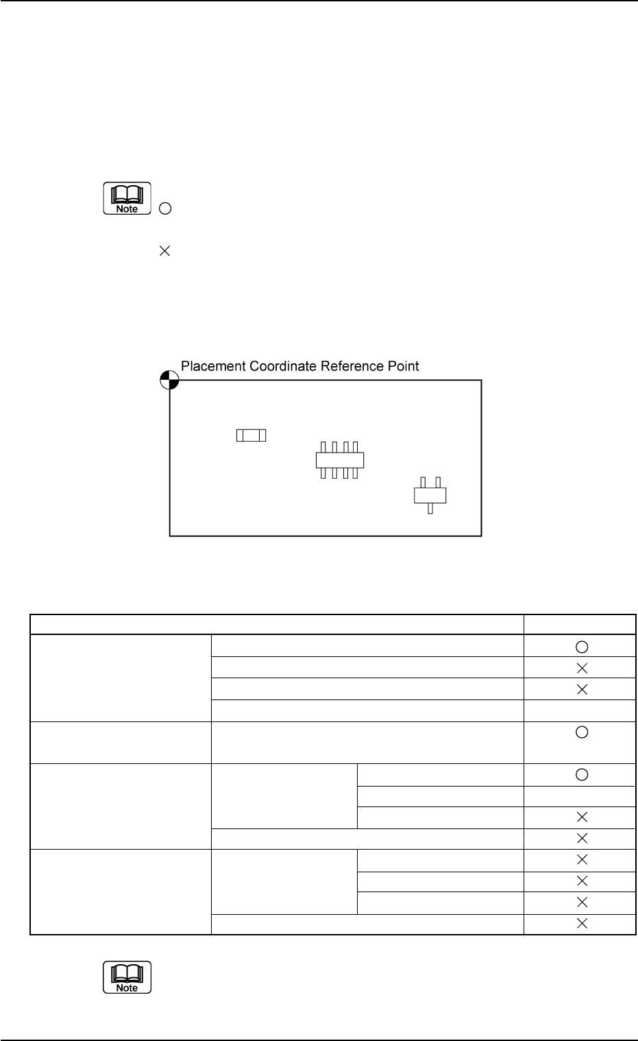
(1) Single Pattern
Fig. 3B2
List of Required Data Table 3B10
Pattern Program Required Data
Operation Data P.C.B. Data
P.C.B. Recognition Data
P.C.B. Recognition Mark Data
Setup Data Note (a)
Placement Feeder Base #1, #3, #4,
Feeder Location Vibratory Stick #1, #2, #3
Placement Data U1 Placement Data (P) Placement Data (P)
Unit Control Note (b)
Unit P.C.B. B.B.R.
Placement Data (O)
Placement Data Un Placement Data (P) Placement Data (P)
Unit Control
Unit P.C.B. B.B.R.
Placement Data (O)
(a) Specify these parameters (data) for automatic adjustment
of the conveyor width.
(b) Specify these parameters (data) according to the situational
changes.
0206-002 2-6 AHB01EDTP
2. Pattern Program