3OM-1075-002.pdf - 第60页
(B01_07) Fdr No. When "Enable" is selected for the feeder alternate function, set the destination feeder No. (Fdr No.) of the feeder that will work in place of the feeder where component pick-up error has occur…
(B01_03) C
Set control commands in the text boxes.
- (hyphen): This command handles the steps as those
for the placement feeder location data.
E: This command shows the end of the placement
feeder location data.
The step where "E" is set is valid.
S: This command invalidates the steps specified as
placement feeder location data.
X: This command invalidates the steps specified as
placement feeder location data and shows the end
of the data.
(B01_04) Comment
A comment can be entered for each feeder No. (Fdr. No.).
Up to 32 characters (alphanumerics and marks) can be
used.
(a) The performance of the machine is not affected by these
commands. In other words, it has nothing to do with or
without these comments.
(b) It is recommended to set helpful information on comments
related to the feeder Nos. (Fdr. Nos.).
(B01_05) Feeder Fixed
Select "Enable" or "Disable" to determine whether or not the
feeder positions should be fixed in place.
When "Enable" is selected, the feeder No. (Fdr. No.) and
the component ID are not affected by any insert and delete
operations of a component.
Disable: The feeder position is not fixed.
Enable: The feeder position is fixed.
(B01_06) Feeder Alternate
Select "Enable" or "Disable" to determine whether or not the
feeder alternate function should be used.
Disable : The feeder alternate function is not used.
Enable : The feeder alternate function is used.
0308-003 2-40
AHB01EDTP
2.4 Placement Feeder Location Data
Fig. 3B68
C
-
Fig. 3B69
Comment
Fig. 3B71
Feeder Alternate
Disable
Fig. 3B70
Feeder Fixed
Disable
If a control command other than the following ones is
used, the step becomes invalid.
CAUTION
(B01_07) Fdr No.
When "Enable" is selected for the feeder alternate function,
set the destination feeder No. (Fdr No.) of the feeder that will
work in place of the feeder where component pick-up error
has occurred in succession.
(B01_08) Library Comment
Displayed is the comment entered in the component library
data.
(B01_09) Dir [deg], Carrier Data Type, Width [mm]
Shown are the values specified in the component library data.
(B01_10) Nozzle #1, C, Nozzle #2, C
Displayed are the nozzle IDs and control commands speci-
fied in the component library data.
0308-004 2-41
AHB01EDTP
2.4 Placement Feeder Location Data
Fig. 3B72
Fdr No.
000 (000)
Fig. 3B72-1
Library Comment
EA06
S
EA04
-
Nozzle #1
C
Nozzle #2
C
Fig. 3B74
Fig. 3B73
Carrier Data Type
24
Width [mm]
Dir [deg]
0
Embossed
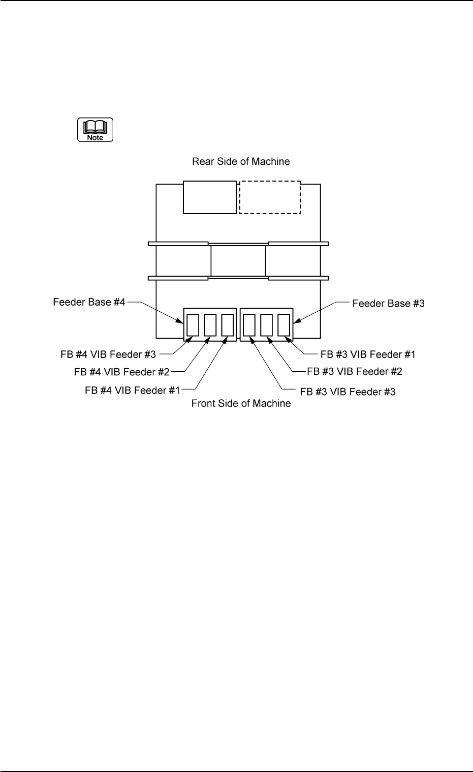
(B02) FB #3 VIB Feeder #1, #2, and #3, FB #4 VIB Feeder #1, #2,
and #3
It can be determined which components must be used and
which carrier stick on the vibratory stick feeders must be
loaded with the selected components.
(a) The following shows the positional relation between the
vibratory stick feeders.
Fig. 3B75
(b) Up to 3 vibratory feeders can be installed on one feeder
base.
(c) Up to 9 carrier sticks can be attached to one vibratory stick
feeder.
2.4 Placement Feeder Location Data
0206-003 2-42 AHB01EDTP