3OM-1075-002.pdf - 第264页
Fig. 3E34 When the rotational center of Head #1 is actually located at the po- sition shown in Fig. 3E34, the offset parameters representing the X (horizontal) must be provided with a minus (-) sign and the offset parame…
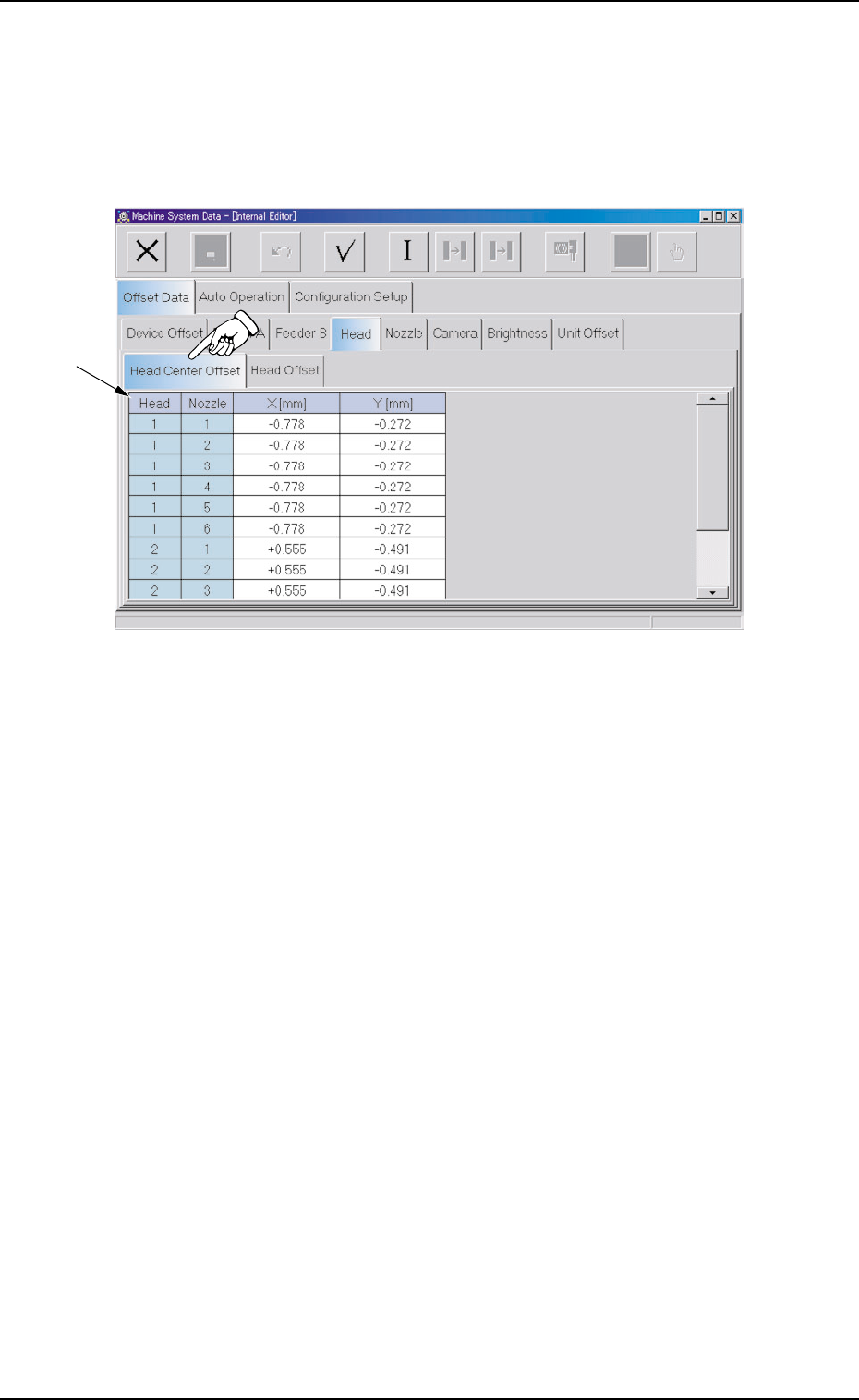
2.1.4.1 "Head Center Offset" Tab
• Sheet Layout
When the "Head Center Offset" tab is pressed in the "Head" tab sheet,
the following tab sheet appears.
Fig. 3E33 "Head Center Offset" Tab Sheet
• Sheet Composition
*1 Offset Items
Set the following offset values.
Head 1 Nozzle 1 through 6
X [mm] (Horizontal) and Y [mm] (Vertical)
The NC axis is rotated such that a nozzle on Head #1 is specified
as Nozzle #1.
This offset data is used to set the distance between the scanning
coordinate center (actual position) of the P.E.C. camera on the beam
and the rotational center of Head #1 (Nozzle #1). The distances
deviating from the design values must be entered in each text box.
The parameters must be those viewed in the coordinate system
(PL-XY) for P.C.B. positioning.
As for Nozzles #2 through #6, the offset data is set in the same way
as Nozzle #1.
2.2 "Auto Operation" Tab
0308-004 5-32 AHB01EDTP
*1
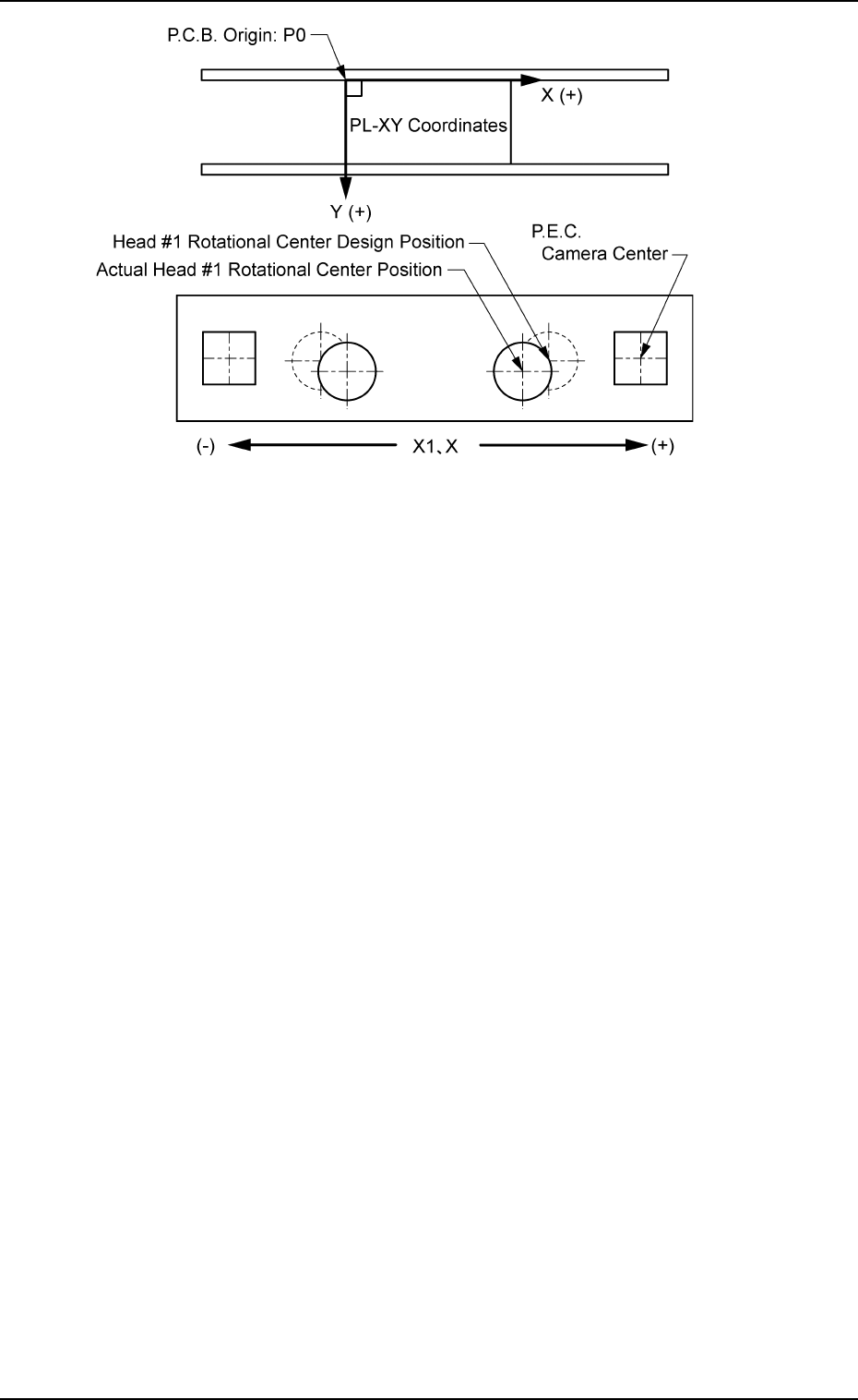
Fig. 3E34
When the rotational center of Head #1 is actually located at the po-
sition shown in Fig. 3E34, the offset parameters representing the X
(horizontal) must be provided with a minus (-) sign and the offset
parameter representing the Y (vertical) with a plus (+) sign.
This offset data is calculated through teaching operation which is
performed, using the jig component stationed at the teaching plate
inside the machine.
2.1 "Offset Data" Tab
0206-003 5-33 AHB01EDTP
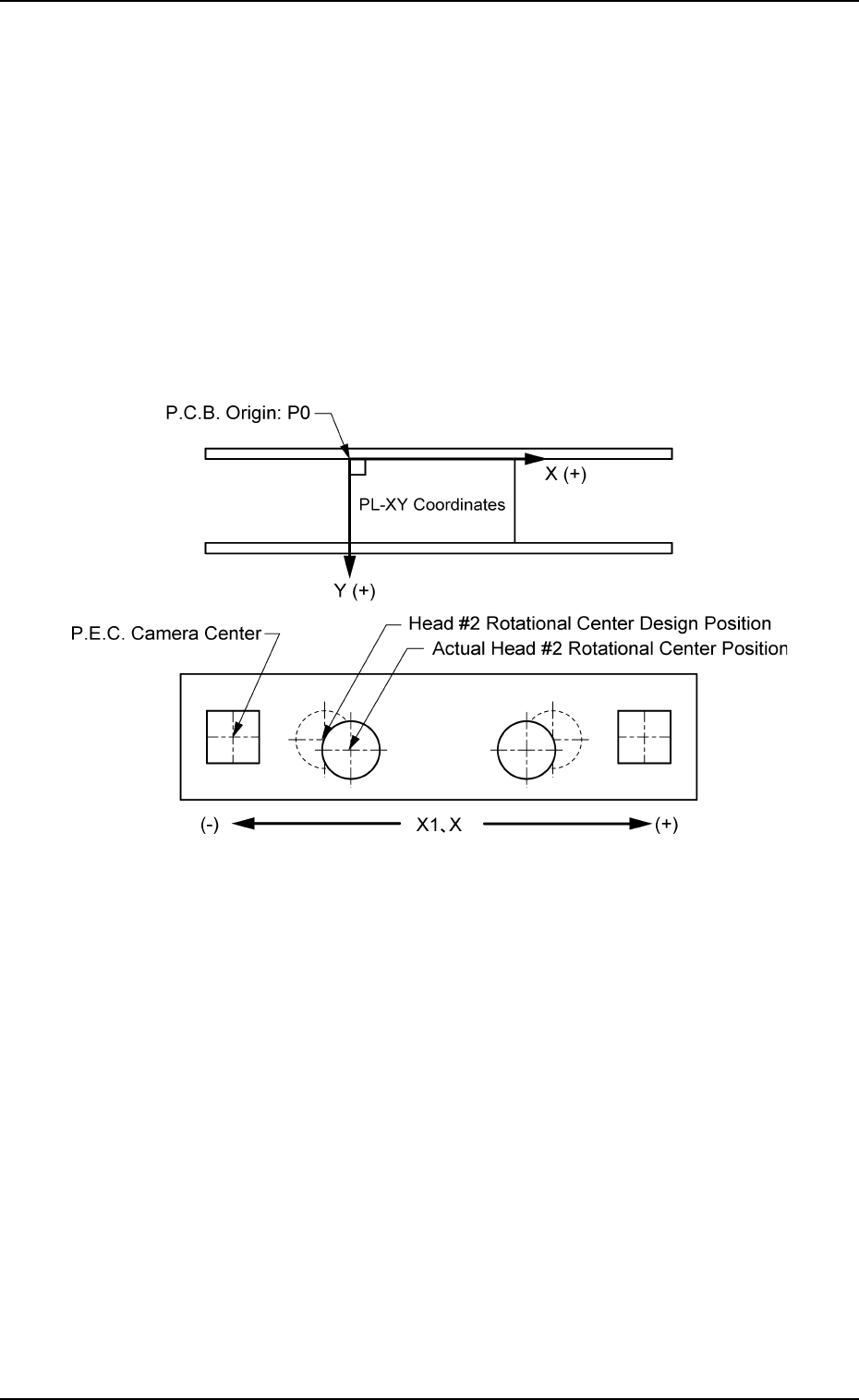
Head 2 Nozzle 1 through 6
X [mm] (Horizontal) and Y [mm] (Vertical)
The NC axis is rotated such that a nozzle on Head #2 is specified
as Nozzle #1.
This offset data is used to set the distance between the scanning
coordinate center (actual position) of the P.E.C. camera on the beam
and the rotational center of Head #2 (Nozzle #1). The distances
deviating from the design values must be entered in each text box.
The parameters must be those viewed in the coordinate system
(PL-XY) for P.C.B. positioning.
As for Nozzles #2 through #6, the offset data is set in the same way
as Nozzle #1.
Fig. 3E35
When the rotational center of Head #1 is actually located at the po-
sition shown in Fig. 3E35, the offset parameter representing the X
(horizontal) must be provided with a minus (-) sign and the offset
parameter representing the Y (vertical) with a plus (+) sign.
This offset data is calculated through teaching operation which is
performed, using the jig component stationed at the teaching plate
inside the machine.
2.1 "Offset Data" Tab
0206-003 5-34 AHB01EDTP