3OM-1075-002.pdf - 第318页
2 . 3 "Configuration Setup" T ab 2.3.1 "Light T ower Setup" T ab The corresponding tab sheet enables the operator to allocate the lamp colors for the light tower and the buzzer sounds. • • • • • Sheet…

Locate conveyor timing
These are items that must be specified in the operation data of
the pattern program data.
"Standard" and "Mode 1 through Mode 9" are provided.
Transfer speed (Low speed) decelerate ratio [%]
The locate conveyor works at two-stage speed.
The locate conveyor receives a P.C.B. at the high transfer
speed and the speed is reduced to the low transfer speed
until the conveyor stops at the locating position.
Set the ratio (%) of the speed deceleration.
The data input range is "0 to 99%".
Decelerate timing [sec]
Set the period of time during which the transfer speed must
be changed from "High" to "Low" after a P.C.B. has been
received at high speed and the P2 sensor has detected the
P.C.B.
The data input range is "0.000 to 9.999 seconds".
Stop timing [sec]
Set the period of time during which the P.C.B. locating posi-
tion sensor detects a P.C.B. and the conveyor stops run-
ning when "P.C.B. Priority" is set in the "P.C.B. locate
method" text box.
The data input range is "0.000 to 9.999 seconds".
Reverse stop timing [sec]
Set the period of time during which the P.C.B. locating posi-
tion sensor detects a P.C.B. and the conveyor stops run-
ning during reverse positioning.
The data input range is "0.000 to 9.999 seconds".
Acceleration ratio [%]
Set the ratio (%) of the speed deceleration compared with
the maximum acceleration of each conveyor.
The data input range is "0 to 99%".
2.2 "Auto Operation" Tab
01 12-001 5-85 AHB01EDTP
2.3 "Configuration Setup" Tab
2.3.1 "Light Tower Setup" Tab
The corresponding tab sheet enables the operator to allocate the lamp
colors for the light tower and the buzzer sounds.
••
••
• Sheet Layout
When the "Light Tower Setup" tab is pressed in the "Configuration Setup"
tab sheet, the following tab sheet appears.
Fig. 3E76 "Light Tower Setup" Tab Sheet
••
••
• Sheet Composition
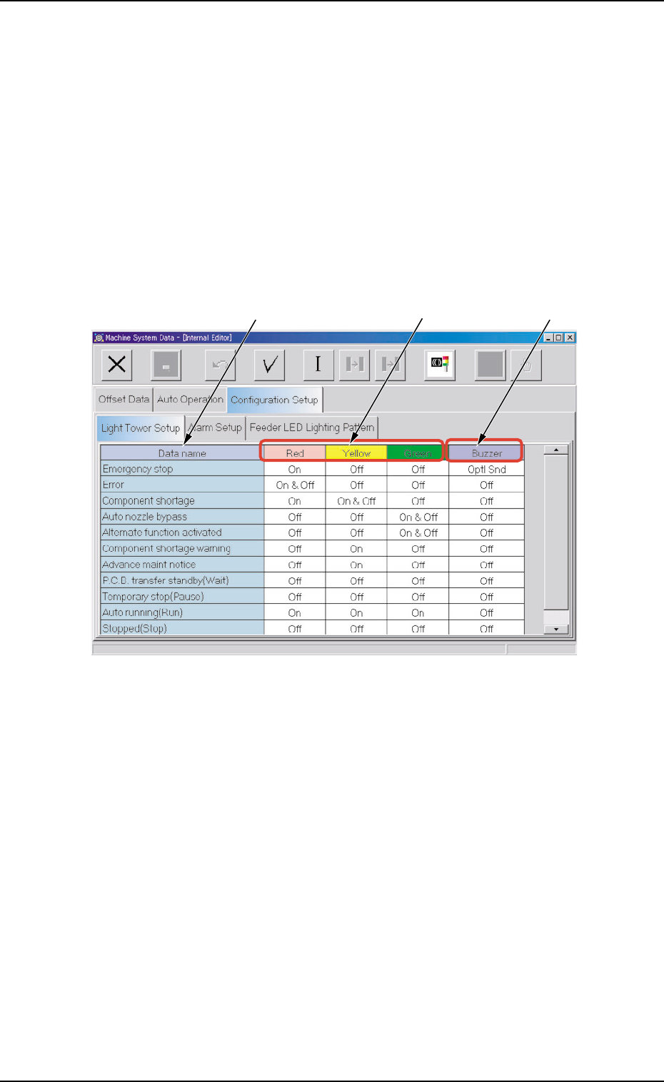
*1 Data name
Displayed are the items for which the colors (red, yellow, and
green) of the tower lights and the types of alarm sounds should
be specified.
*2 Red, Yellow, Green
Set "On", "On & Off", or "Off" in each text box to specify the tower
lights (red, yellow, and green).
*3 Buzzer
Set "Off", "Intmt Snd", "Cont Snd", or "Optl Snd" in each text box
to specify the types of alarm sounds.
The desired sound patterns can be made, using the "Alarm Setup"
tab sheet.
*1
*2
*3
0308-003 5-86 AHB01EDTP
2.3 "Configuration Setup" Tab
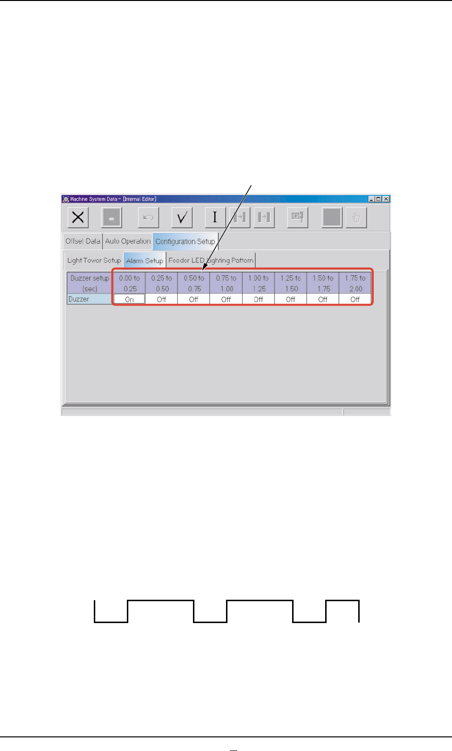
2.3.2 "Alarm Setup" Tab
When "Optl Snd" is selected in a "Buzzer" text box of the "Light Tower
Setup" tab sheet, a pattern of the buzzer sounds must be specified.
••
••
• Sheet Layout
When the "Alarm Setup" tab sheet is pressed in the "Configuration Setup"
tab sheet, the following tab sheet appears.
Fig. 3E77 "Alarm Setup" Tab Sheet
••
••
• Sheet Composition
*1 Time Items
An optional alarm sounds in a cycle of 2 seconds. The 2 sec-
onds is divided into 8 intervals and each interval is assigned as
"ON" or "OFF" to make a sound of your own.
Fig. 3E77-1 Example of Buzzer Sound Setting
0308-003 5-87 AHB01EDTP
2.3 "Configuration Setup" Tab
*1
OFF OFF
ON ON ON ON ON
OFF