3OM-1075-002.pdf - 第329页
Fig. 3E84 *9 Eccentric Distance X [mm], Y [mm] In the case of the special nozzle whose tip is manufactured eccen- trically from the head rotational center , set the eccentricity (distances) separately for the "X&quo…
01 12-001 5-95 AHB01EDTP
*6 Fiducial Mark Image
Specify how (bright or dark) the image of the nozzle tip is cap-
tured in the front lighting system.
Select one of the following options.
Bright or Dark
(a) The set parameter is required for nozzle masking in the
front lighting system.
(b) In normal cases, set "Bright" in each text box.
*7 Lighting Method
Specify which lighting method can be used for each nozzle.
Select one of the following options.
Back-Lighting, Front-Lighting, Back/Front
"Front-Lighting" must be selected for such a nozzle that the
image of the area other than the nozzle tip appears dark in the
back lighting system.
"Back-Lighting" must be selected for such a nozzle that the
image of the area other than the nozzle tip appears bright in the
front lighting system.
*8 V-Groove Size [mm]
When the V-grooved nozzle is used for cylindrical components, set
the size of the V groove in the corresponding text box.
Data Input Range
00.00 to 18.00
In the case of the nozzle without a V groove, set "0" (zero) in the
corresponding text box.
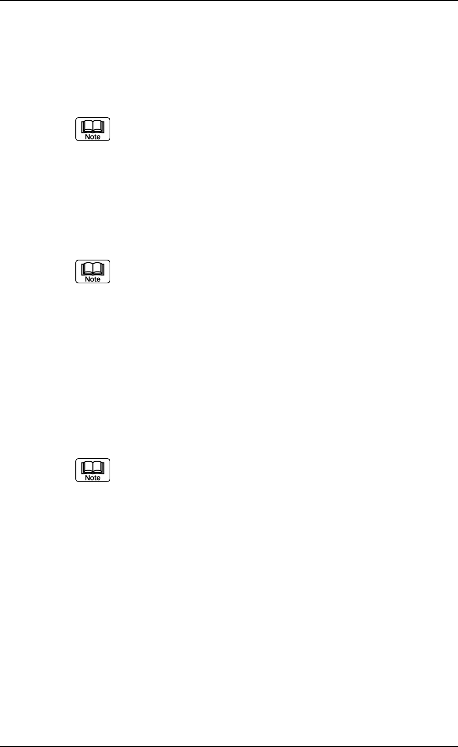
3.2 "Nozzle Data" Tab
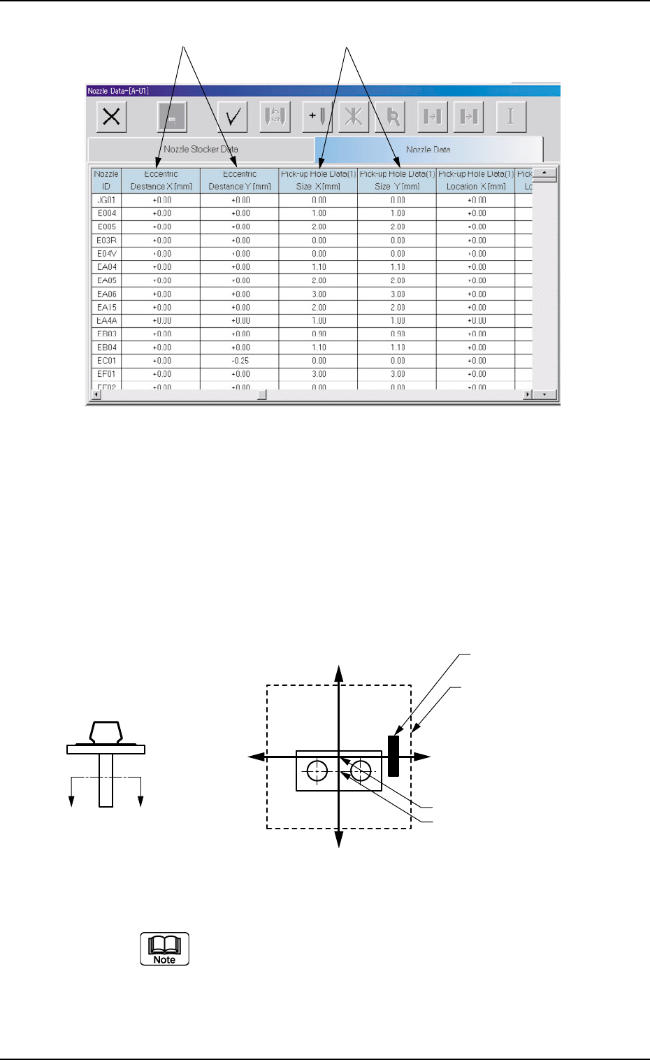
Fig. 3E84
*9 Eccentric Distance X [mm], Y [mm]
In the case of the special nozzle whose tip is manufactured eccen-
trically from the head rotational center, set the eccentricity (distances)
separately for the "X" and "Y" directions.
Data Input Range
X: −99.99 to +99.99
Y: −99.99 to +99.99
Fig. 3E85
(a) Set "0, 0" as the data values (X, Y) for all the standard
nozzles.
(b) By pressing one of the titles (the labels arranged on
top of the list), the parameters can be sorted by "Nozzle
ID", "Length [mm]" , etc., and reorganized, depending
on which title is selected.
3.2 "Nozzle Data" Tab
0206-002 5-96 AHB01EDTP
*9
*10
X(+)
Y (-)
Y (+)
X(-)
A′
A
Diffusion Plate
Imprinted Nozzle ID
Nozzle Center
Nozzle Rotational Center
*10 Pick-up Hole Data (1), (2), (3), and (4)
Size X [mm], Size Y [mm]
Set the dimensions of the nozzle pick-up holes in the text boxes.
Data Input Range
X: 00.00 to 18.00
Y: 00.00 to 18.00
In the case of "Circle", set the same dimensions for "X" and
"Y".
In the case of "Rectangle", set Dimensions X and Y.
Fig. 3E86
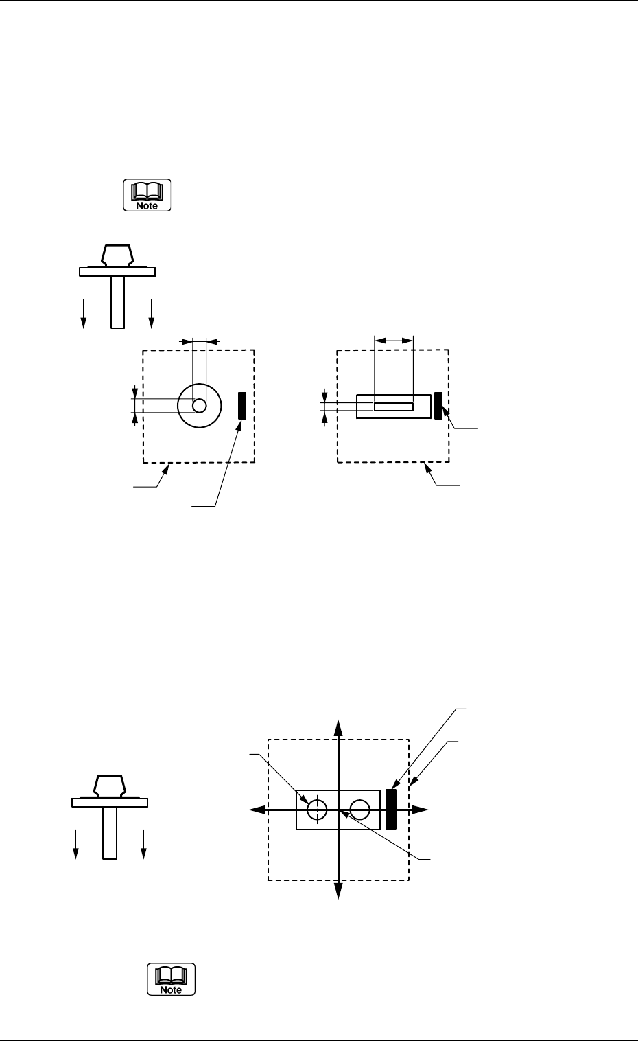
*11 X[mm], Y[mm]
Set the center position (based on the nozzle center) of the pick-
up hole (1) in the text boxes.
Data Input Range
X: -99.99 to +99.99
Y: -99.99 to +99.99
Fig. 3E87
When the pertinent hole is not found, set "00.00" for both
"X" and "Y".
Parameters can be specified for up to 4 pieces of pick-
up holes.
3.2 "Nozzle Data" Tab
0206-002 5-97 AHB01EDTP
X
Y
X
Y
Aѳ
A
Imprinted Nozzle ID
Imprinted Nozzle ID
Diffusion Plate Diffusion Plate
X(-)
Y (+)
Y (-)
X(+)
A′
A
Diffusion Plate
Imprinted Nozzle ID
Pick-up Hole (1)
Nozzle Center