3OM-1075-002.pdf - 第308页
Bfr pos const transfer offset [mm] The parameters (Locate mode, Y clamp timer [sec], Z clamp timer [sec], Conveyor buffer setup, and P .C.B. detection off delay time [sec]) can be specified for the P .C.B. positioning se…

01 12-001 5-75 AHB01EDTP
2.2 "Auto Operation" Tab
Input conveyor
Timer #1 [sec], Timer #2 [sec], Buffer setup, Bfr pos const
transfer, and Bfr pos const transfer offset [mm]
Set each parameter to specify how the input conveyor should work.
Timer #1 [sec]
Set the time to limit the operating time (P.C.B. reception from the
input machine) of the input conveyor.
This timer measures the operating time of the input conveyor
and is used to detect an interrupted P.C.B.
(a) Add 2 seconds (approx.) to the time required for
P.C.B. reception from the input machine and set the
time in the text box.
(b) The data input range is "0 to 99 seconds".
Timer #2 [sec]
Set the time to limit the operating time of the input conveyor to
transfer a P.C.B. on the main machine side.
This timer measures the operating time of the input conveyor
and is used to detect an interrupted P.C.B.
The data input range is "0 to 99 seconds".
Buffer setup
Determine whether or not the P.C.B.’s should be buffered on
the input conveyor.
Set "Enable" or "Disable" in the text box.
Bfr pos const transfer
Determine whether or not the constant P.C.B. transfer system
should be used or not. When the system is used, the constant
number of P.C.B.’s (detected by the P.C.B. detection L1 sen-
sor) are transferred to the buffering position on the input con-
veyor without the P.C.B. detection L2 sensor being used.
Set "Enable" or "Disable" in the text box.
"Enable" improves the productivity.

Bfr pos const transfer offset [mm]
The parameters (Locate mode, Y clamp timer [sec], Z clamp timer
[sec], Conveyor buffer setup, and P.C.B. detection off delay time
[sec]) can be specified for the P.C.B. positioning section.
Locate mode
Set the sequence in which a P.C.B. should be transferred and
positioned. Select "Priority P.C.B. Flow" or "Placement reference".
"Priority P.C.B. Flow"
Select this when the placement coordinate reference for the
P.C.B. must be specified on the opposite side of the P.C.B.
stopper location for P.C.B. positioning.
"Placement reference"
Select this when the placement coordinate reference must be
specified on the side where the P.C.B. is pushed against the
P.C.B. stopper.
Push the P.C.B. against the P.C.B. stopper for position-
ing.
When an area of the P.C.B. has a cutout, etc., and is
pushed against the P.C.B. stopper, the P.C.B. cannot be
positioned correctly.
0206-002 5-76
AHB01EDTP
2.2 "Auto Operation" Tab
Outline of Positioning Operation
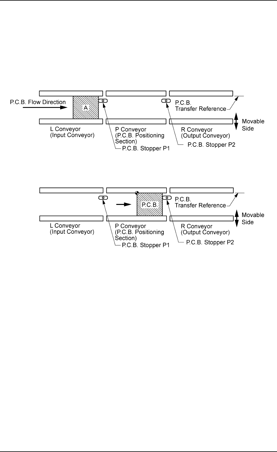
"Priority P.C.B. Flow"
P.C.B.’s are positioned based on the stopper located ahead in
the P.C.B. flow direction.
(1) The P.C.B.’s at "Area A" (standby position) in the figure be-
low are sent to the P.C.B. stoppers.
(2) The P.C.B. backup base ascends and works to position the
P.C.B. vertically.
Fig. 3E68
Fig. 3E69
0206-002 5-77 AHB01EDTP
2.2 "Auto Operation" Tab