3OM-1075-002.pdf - 第68页
Recog Coord X1 [mm], Recog Coord Y1 [mm] Set the X1 and Y1 coordinates of the first fiducial mark based on the pattern origin. Unit: mm Recog Coord X2 [mm], Recog Coord Y2 [mm] Set the X2 and Y2 coordinates of the second…
(C02_02) Unit P.C.B. B.B.R.
Select one of the following options to determine whether or
not the unit P.C.B. B.B.R. function should be used.
Disable : The unit P.C.B. B.B.R. function is not used.
Enable : The unit P.C.B. B.B.R. function (2-point rec-
ognition) is used.
• When "Enable" is set, the recognition coordinate differ as
shown below in (1) according to the parameter set in the
"P.E.C. recognition mode image" text box (described in
"(A02_01) P.E.C. recognition function"). Refer to "(A02)
P.E.C. Recognition Data" in "2.3 Operation Data".
Options for Image Recognition Mode
(1) The following is based on the parameter "Enable" (Nor-
mal Image Recognition Mode).
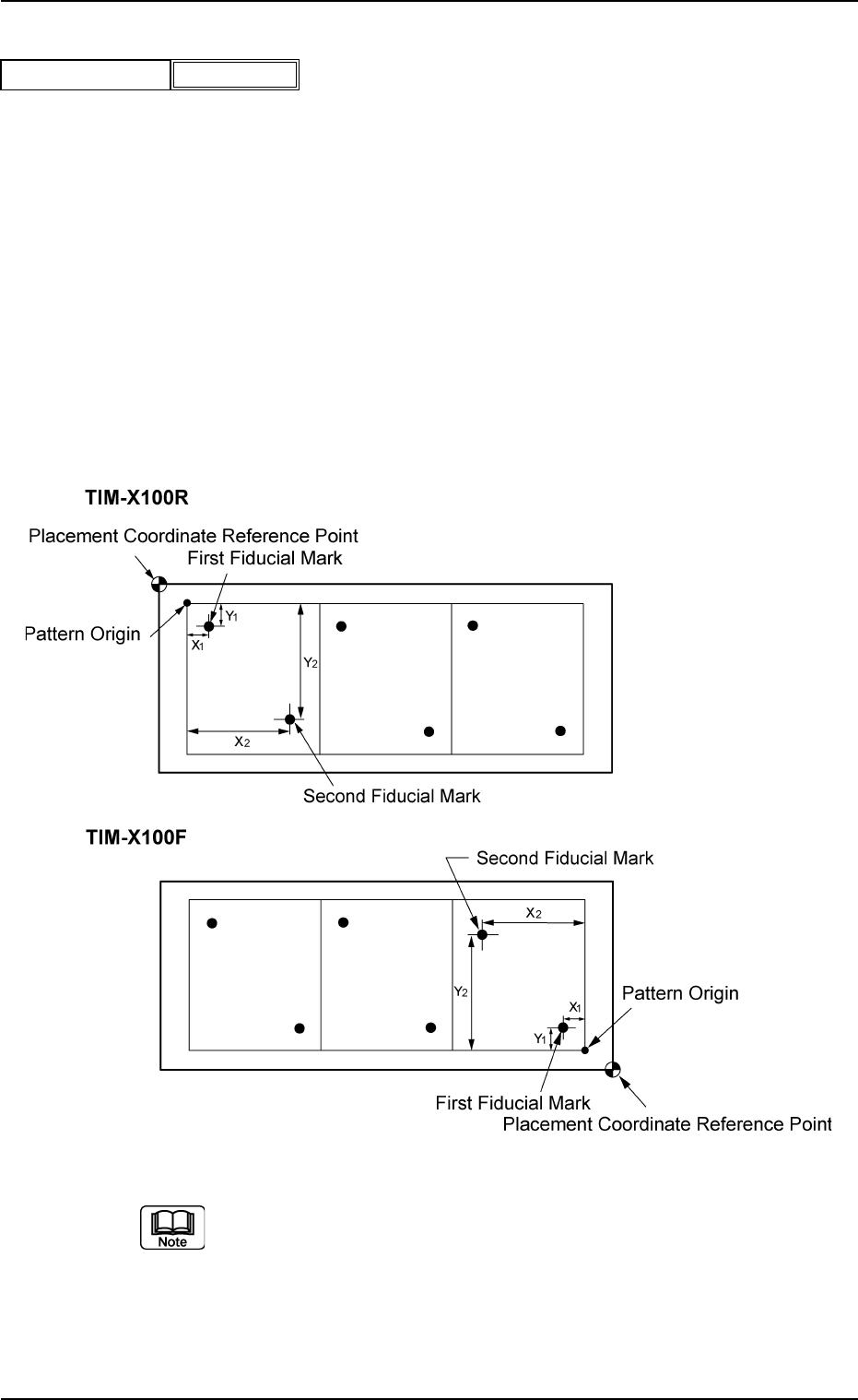
Fig. 3B95 Example of Unit P.C.B. B.B.R. Recognition
(a) Refer to "2. Various Functions" (Section 2) in "Vol. 2: Op-
eration (Supervisor)" for details.
(b) The pattern origin (coordinates) must be located inside the
placement coordinate reference point (coordinates).
(c) Determine the coordinates of the first and second fiducial
marks for the unit P.C.B. B.B.R. recognition function.
2.5 Placement Data
Unit P.C.B. B.B.R.
Fig. 3B94
Disable
0206-002 2-48 AHB01EDTP
Recog Coord X1 [mm], Recog Coord Y1 [mm]
Set the X1 and Y1 coordinates of the first fiducial mark based
on the pattern origin.
Unit: mm
Recog Coord X2 [mm], Recog Coord Y2 [mm]
Set the X2 and Y2 coordinates of the second fiducial mark
based on the pattern origin.
Unit: mm
Fiducial Mark FM1, Fiducial Mark FM2
Set the mark Nos. of the first and second fiducial marks
FM1 and FM2.
Select the mark Nos. (Mark #) specified in the P.C.B. recog-
nition mark data of the operation data.
(C02_03) P-No.
Shown are the step Nos. of the placement data (P).
Set coordinates and angles for component placement in the
lines of the step Nos. (P-Nos.).
2.5 Placement Data
Fig. 3B96
Recog Coord Y1 [mm]
Recog Coord X1 [mm]
000.000
000.000
Fig. 3B97
Recog Coord Y2 [mm]
Recog Coord X2 [mm] 100.000
100.000
0206-002 2-49 AHB01EDTP
01
01
Fiducial Mark FM1
Fig. 3B98
Fiducial Mark FM2
Fig. 3B99
P-No.
1
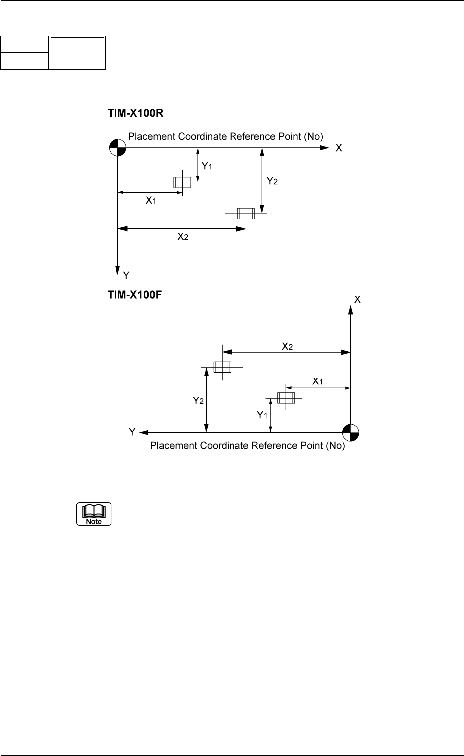
(C02_04) X [mm], Y [mm]
Set Coordinates X and Y for component placement.
The coordinates must be based on the placement coordi-
nate reference point (N
0
).
Unit: mm
Fig. 3B101
Do not set any coordinates for component placement in the last
line (last step No.).
Keep them as "000.00".
0206-002 2-50
AHB01EDTP
2.5 Placement Data
X [mm]
Fig. 3B100
Y [mm]
010.00
010.00