3OM-1075-002.pdf - 第171页
AHB01EDTP 0308-003 3-35 3.3 "Recognition Data" T ab Fig. 3C23-1 "Recognition Data" T ab Sheet ("BGA/CSP" Selected) *7 Electd pos detn Electd pos tol [mm] When "Enable (Mnl)" is set…
AHB01EDTP
3.3.3 BGA/CSP
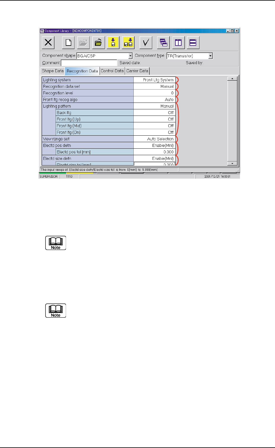
Fig. 3C23 "Recognition Data" Tab Sheet ("BGA/CSP" Selected)
••
••
• Sheet Composition
Each parameter is displayed or can be entered.
Refer to "4.1.3 Basic Usage of Text Boxes" in "Section 2" for the
detailed information on how to enter parameters.
*1 Lighting system, *2 Recognition data set, *3 Recognition
level, *4 Back ltg recog algo (Front ltg recog algo), *6 View range
set
"Back ltg recog algo" or "Front ltg recog algo" appears in *4
according to the parameter selected in the "Lighting system"
text box.
*5 Lighting pattern
Back ltg, Front ltg (Up), Front ltg (Mid), Front ltg (Dn)
When "Manual" is set in the "Ltg pattern designation" text box, it is
required to enter parameters in these text boxes.
0206-003 3-34
3.3 "Recognition Data" Tab
*5
*1
*2
*6
*7
*8
*3
*4
AHB01EDTP
0308-003 3-35
3.3 "Recognition Data" Tab
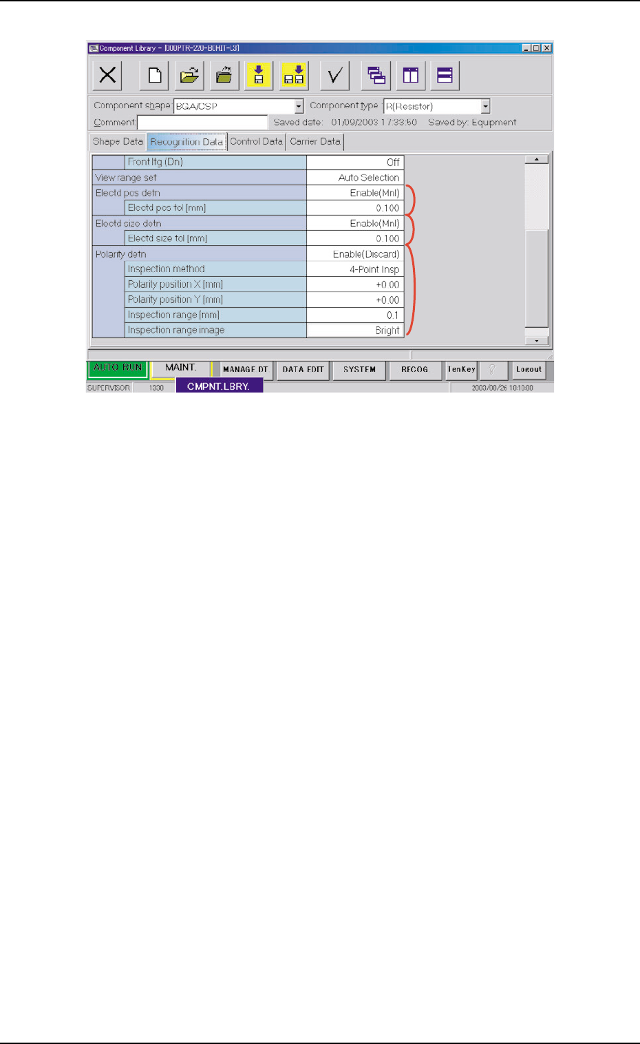
Fig. 3C23-1 "Recognition Data" Tab Sheet ("BGA/CSP" Selected)
*7 Electd pos detn
Electd pos tol [mm]
When "Enable (Mnl)" is set in the "Electd pos detn" text box, it is
required to enter a parameter in this text box.
*8 Electd size detn
Electd size tol [mm]
When "Enable (Mnl)" is set in the "Electd size detn" text box, it is
required to enter a parameter in this text box.
*9 Polarity detn
Inspection method, Polarity position X [mm], Polarity position Y [mm],
Inspection range [mm], and Inspection range image
When "Enable (Discard)" or "Enable (Placement)" is selected in the
"Polarity detn" text box, it is required to enter a parameter in each
text box.
*9
*7
*8
AHB01EDTP
3.4 "Control Data" Tab
The corresponding tab sheet appears when "Cylindrical", "Square", "De-
form (Simple)", "Deform (Complex)", "Connector (Simple)", "Connector
(Complex)", "Other Leaded (Simple)", "Other Leaded (Complex)", or
"BGA/CSP" is selected in the "Component shape" text box.
••
••
• Sheet Layout
When the "Control Data" tab is pressed, the "Control Data" tab sheet
appears.
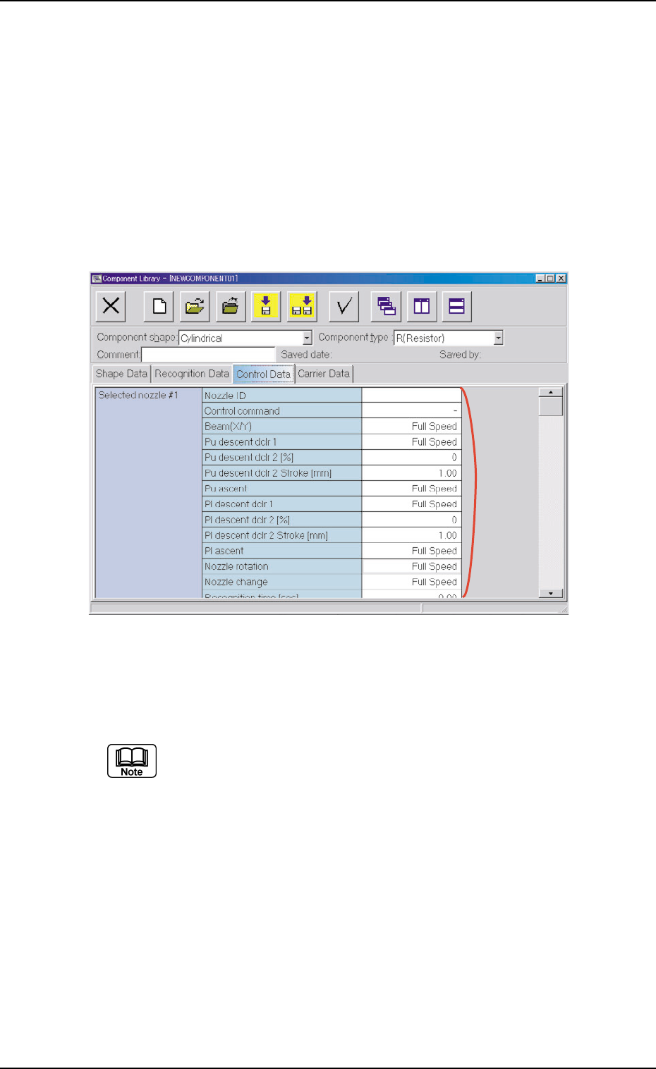
Fig. 3C24 "Control Data" Tab Sheet ("Cylindrical" Selected)
••
••
• Sheet Composition
Each parameter is displayed or can be entered.
Refer to "4.1.3 Basic Usage of Text Boxes" in "Section 2" for the
detailed information on how to enter parameters.
*1 Selected nozzle #1
Control command
Nozzle ID, Beam (X/Y), "Pu descent dclr 1", Pu descent dclr 2
[%], Pu descent dclr 2 Stroke [mm], Pu ascent, Pl descent dclr
1, Pl descent dclr 2 [%], Pl descent dclr 2 Stroke [mm], Pl as-
cent, Nozzle rotation, Nozzle change, Recognition time [sec],
Pu retention time [sec], Pl retention time [sec], Mvbl recog
retention time [sec], Fxd recog retention time [sec], Cmpnt
detection (Sensor), Air blow, and Air blow off timing [mm]
When "-" is set in the "Control command" text box, it is required to
enter parameters in these text boxes.
3.4 "Control Data" Tab
0308-004 3-36
*1