3OM-1075-002.pdf - 第281页
2.1.6.2 "Component Recog Fixed Camera" T ab • Sheet Layout When the "Component Recog Fixed Camera" tab is pressed in the "Camera" tab sheet, the following tab sheet appears. Fig. 3E50 "…
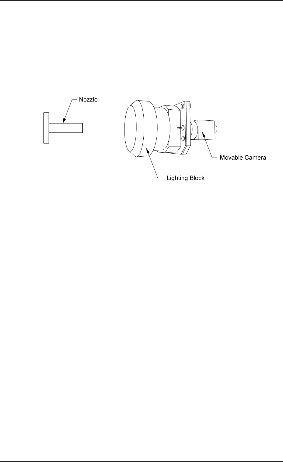
X [mm] (Horizontal), Y [mm] (Vertical), and Z [° ] for "Z=0° " (Z
Axis) or "Z=180° (Z Axis)"
The set offset parameters are used to adjust the positional and an-
gular deviations compared with the design dimensions of the com-
ponent recognition movable cameras (viewed from the nozzle posi-
tion where the NC axis is rotated by 90° from the angle at which a
component is picked up to be recognized).
(X: Horizontal, Y: Vertical, and Z: Angle)
Fig. 3E49
2.1 "Offset Data" Tab
0206-003 5-48 AHB01EDTP
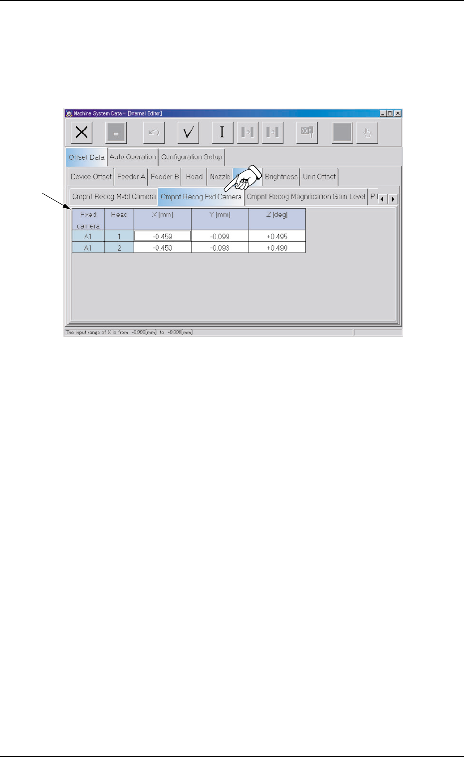
2.1.6.2 "Component Recog Fixed Camera" Tab
• Sheet Layout
When the "Component Recog Fixed Camera" tab is pressed in the
"Camera" tab sheet, the following tab sheet appears.
Fig. 3E50 "Component Recog Fixed Camera" Tab Sheet
• Sheet Composition
*1 Offset Items
Set the offset values for Heads #1 and #2 related to Fixed Camera
A1.
2.1 "Offset Data" Tab
0308-004 5-49 AHB01EDTP
*1
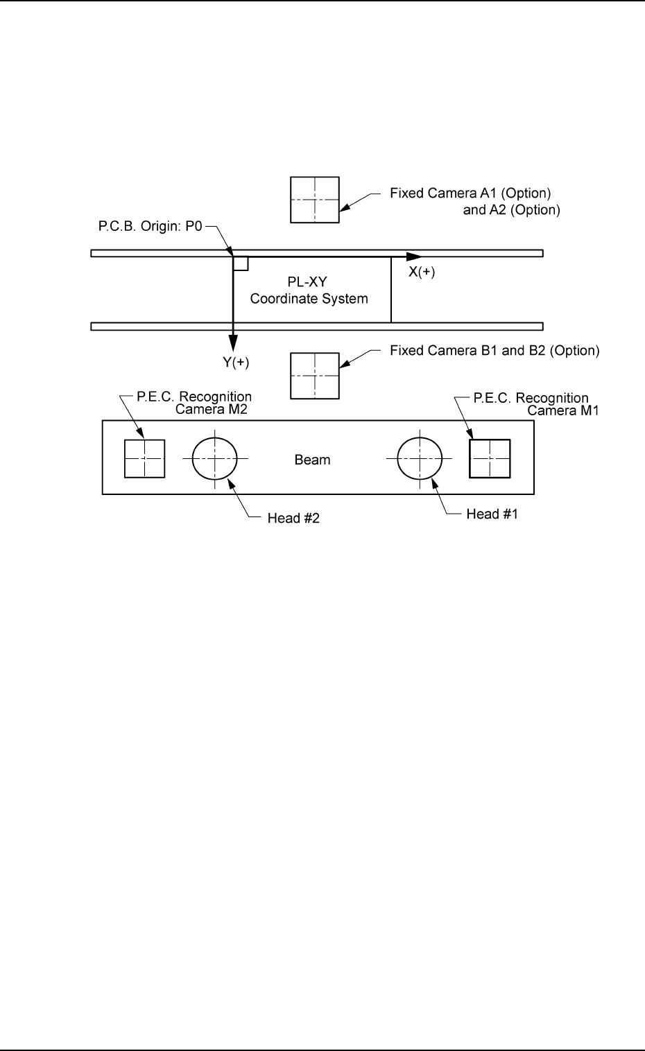
X [mm] (Horizontal), Y [mm] (Vertical), and Z [° ] (Angle)
This offset data is used to adjust the positional and angular devia-
tions compared with the design dimensions of the component rec-
ognition fixed camera center positions (viewed from the P.C.B. po-
sitioning reference (PL-XY Coordinates: Origin P0)). The value based
on the PL-XY coordinate system must be entered in each text box.
Fig. 3E51
This offset data is automatically calculated through teaching opera-
tion which is performed, using the P.E.C. recognition camera on
Head #1.
2.1 "Offset Data" Tab
0206-003 5-50 AHB01EDTP