3OM-1075-002.pdf - 第285页
Magnification X [0.01 µ µ µ µ µ m/pixel] (Horizontal) and Magnification Y [0.01 µ µ µ µ µ m/pixel] (V ertical) for Each Camera (P1 and P2) These parameters are used to set the magnifications of the P .E.C. recognition ca…
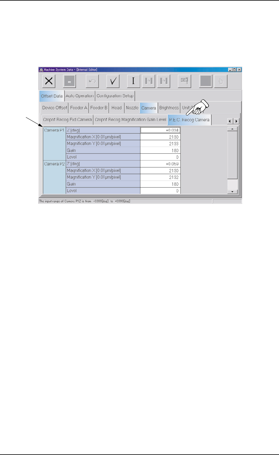
2.1.6.4 "P.E.C. Recog Camera" Tab
• Sheet Layout
When the "P.E.C. Recog Camera" tab is pressed in the "Camera"
tab sheet, the following tab sheet appears.
Fig. 3E53 "P.E.C. Recog Camera" Tab Sheet
• Sheet Composition
*1 Offset Items
Set the following offset values.
Z [deg] for Each Camera (P1 and P2)
The set parameters are used to adjust the horizontal swing of the
P.E.C. recognition cameras on the beam.
Set parameters representing the angular deviations in the scanning
coordinates of the cameras based on the P.C.B. positioning X/Y
coordinates (PL-XY coordinates: Origin P0).
When the camera scanning coordinates shift to the P.C.B. position-
ing X/Y coordinates system counterclockwise, the sign becomes
"Plus".
2.1 "Offset Data" Tab
0308-004 5-52 AHB01EDTP
*1

Magnification X [0.01
µµ
µµ
µm/pixel] (Horizontal) and Magnification
Y [0.01
µµ
µµ
µm/pixel] (Vertical) for Each Camera (P1 and P2)
These parameters are used to set the magnifications of the P.E.C.
recognition cameras in increments of 0.01 µm per pixel.
The parameters are automatically calculated through teaching op-
eration which is performed, using the jig for magnification measure-
ment.
Refer to "5.3 "P.E.C. Recog Camera & Beam Offset" Tab" of "Sec-
tion 6" in "Vol. 2: Operation (Supervisor)" for details.
Gain and Level for Each Camera (P1 and P2)
These parameters are used to set amplifications at which the im-
age signals of the image captured by the P.E.C. recognition cam-
eras are converted into the picture information representing bright-
ness.
The defaults are "180" for "Gain" and "0" (zero) for "Level" and re-
garded as standard gain and level.
(a) The lower the gain is, the better the contrast becomes.
(b) The smaller the level is, the brighter the whole view
becomes.
2.1 "Offset Data" Tab
0206-002 5-53 AHB01EDTP
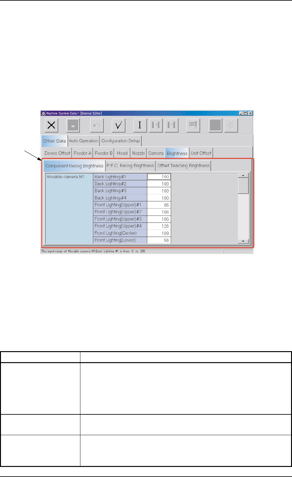
2.1.7 "Brightness" Tab
This tab sheet must be used only by our service personnel.
It is not required to enter any parameters because they are automati-
cally taught.
• Sheet Layout
When the "Brightness" tab is pressed in the "Offset Data" tab sheet,
the following tab sheet appears.
Fig. 3E54 "Brightness" Tab Sheet
• Sheet Composition
*1 Tabs and Tab Sheets
The "Brightness" tab sheet is provided with the following 3 tabs.
When each tab is pressed, the corresponding tab sheet appears.
Table 3E9
Tabs Description
Component Recog The corresponding tab sheet enables the operator to set the bright-
Brightness ness of the lighting units on the component recognition cameras (M1,
M2, B1, and B2).
The four lighting units should be adjusted such that they emit lights
having almost the same brightness.
P.E.C. Recog Brightness The corresponding tab sheet enables the operator to set the bright-
ness of the lighting units on P.E.C. Recognition Cameras P1 and P2.
Offset Teaching The corresponding tab sheet enables the operator to set the bright-
Brightness ness (based on the reflection of light emitted from the lighting unit for
offset teaching operations) through automatic teaching operations.
2.1 "Offset Data" Tab
0308-003 5-54 AHB01EDTP
*1