3OM-1075-002.pdf - 第39页
(A01_07) P .C.B. positioning reference Displayed is a P .C.B. positioning reference point. Rear Left : P .C.B.’s are positioned based on the rear left corner . Front Left : P .C.B.’s are positioned based on the front lef…

(A01_06) Placement mode (Not Available)
Set "Placement" or "Pass" in the text box.
In normal cases, select "Placement".
When "Pass" is set in this text box and the pattern program
data is selected as current one, the vacuum pump motor is
automatically turned off.
0206-002 2-19
AHB01EDTP
2.3 Operation Data
Placement mode
Fig. 3B23
Placement
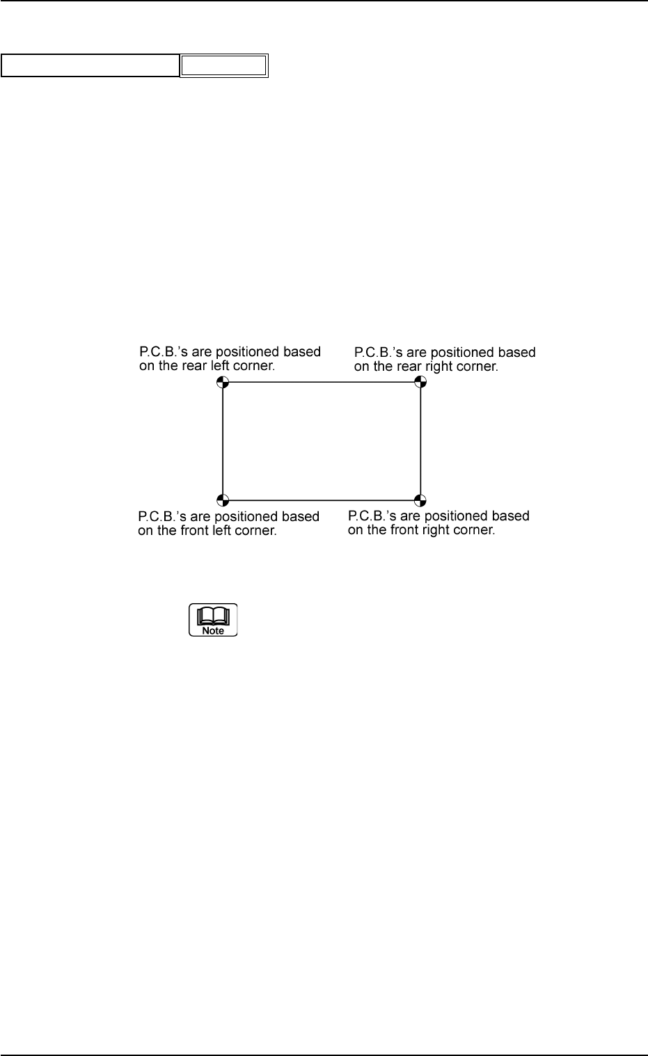
(A01_07) P.C.B. positioning reference
Displayed is a P.C.B. positioning reference point.
Rear Left : P.C.B.’s are positioned based on the rear left
corner.
Front Left : P.C.B.’s are positioned based on the front left
corner.
Front Right : P.C.B.’s are positioned based on the front
right corner.
Rear Right : P.C.B.’s are positioned based on the rear right
corner.
Fig. 3B25
(a) TIM-X100R is based on "Rear Left" or "Rear
Right".
TIM-X100F is based on "Front Left" or "Front
Right".
(b) The P.C.B. positioning reference must be
changed when the pattern program (prepared
for the machine that requires a different P.C.B.
positioning reference) is used.
0206-003 2-20 AHB01EDTP
2.3 Operation Data
P.C.B. positioning reference
Fig. 3B24
Rear Left

(A01_08) P.C.B. locate
Datum
Select one of the following options as a P.C.B. positioning
reference.
Outline : The P.C.B.’s are positioned based on the out-
line.
Hole : This is an optional function.
The reference pin for positioning is aligned with
the P.C.B. hole position to position the P.C.B.’s.
(a) In normal cases, set "Outline" in the text box.
(b) "Hole" may not be used according to the combination of
the P.C.B. flow direction and the positioning reference po-
sition. It depends on the value specified in the "X [mm]" text
box of the label "P.C.B. size".
Please contact us when the "Hole" reference is used.
Sequence
Select one of the following options as a P.C.B. positioning
sequence.
Standard:
Y Clamp deactivated, Z Clamp activated, and BPC Axis
activated
Z clamp & Y Pusher:
Y Clamp activated once, Z Clamp activated, and BPC
Axis activated
Conveyor timing
Set how to use the following parameters specified in
the "Parameter 2" tab sheet. (Operation Sequence:
[SYSTEM] Button Æ "SYS DATA" Menu Æ "Auto Op-
eration" Tab Æ "Transfer Conveyor" Tab Æ "Parameter
2" Tab Sheet)
Transfer speed (Low speed) decelerate ratio [%], De-
celerate timing [sec], Stop timing [sec], Revers stop
timing [set], and Acceleration ratio [%]
Standard:
This parameter is used in normal cases.
Mode 1:
This is the parameter adjusted and reserved exclusively
for the jig P.C.B.
0308-004 2-21
AHB01EDTP
2.3 Operation Data
Fig. 3B26
Outline
Standard
Standard
P.C.B. locate
Datum
Sequence
Conveyor timing