3OM-1075-002.pdf - 第275页
2.1.5.4 "Nozzle Center" T ab • Sheet Layout When the "Nozzle Center" tab is pressed in the "Nozzle" tab sheet, the following tab sheet appears. Fig. 3E45 "Nozzle Center" T ab Sheet…
When values are entered with a plus (+) sign, the nozzle change
positions are changed to "X (+)" and "Y (+)" shown below.
Fig. 3E43
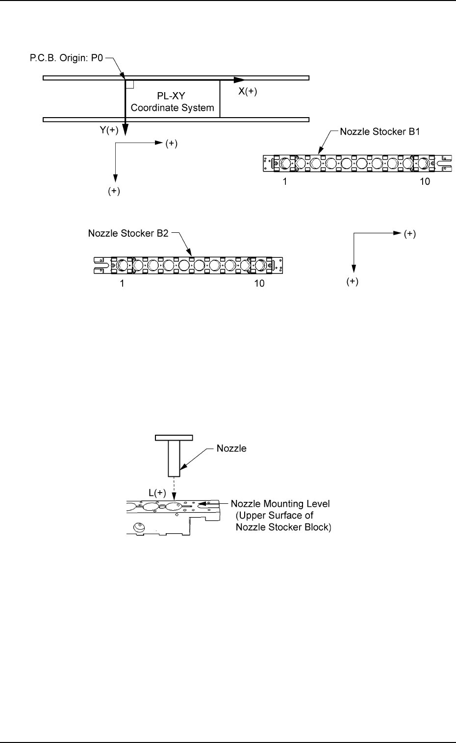
Head (1 and 2) and Address (1 through 10)
L [mm] (Height)
When an offset value is set with a plus (+) sign, the nozzle change
position (height) is changed to "L (+)" shown below, concluding that
the descending stroke has increased.
Fig. 3E44
2.1 "Offset Data" Tab
0206-003 5-42 AHB01EDTP
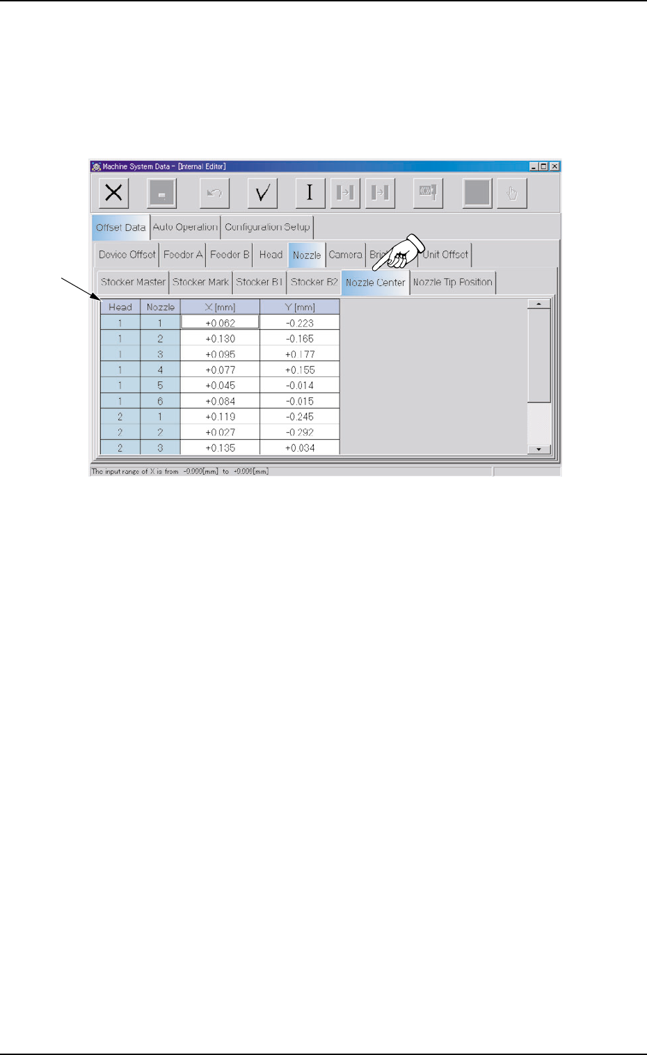
2.1.5.4 "Nozzle Center" Tab
• Sheet Layout
When the "Nozzle Center" tab is pressed in the "Nozzle" tab sheet,
the following tab sheet appears.
Fig. 3E45 "Nozzle Center" Tab Sheet
• Sheet Composition
*1 Offset Items
Set the following offset values.
Head (1 and 2) and Nozzle (1 through 6)
X [mm] (Horizontal) and Y [mm] (Vertical)
Set the offset data to adjust the deviations between the head rota-
tional center and the nozzle ends (the center of the diffusion plate).
2.1 "Offset Data" Tab
0308-004 5-43 AHB01EDTP
*1
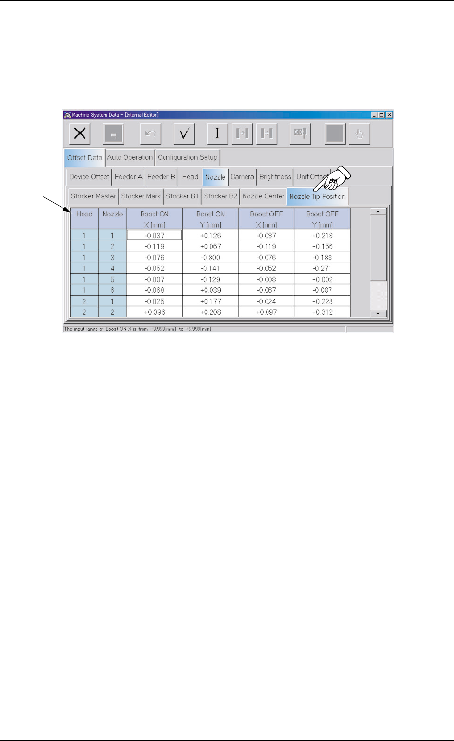
2.1.5.5 "Nozzle Tip Position" Tab
• Sheet Layout
When the "Nozzle Tip Position" tab is pressed in the "Nozzle" tab
sheet, the following tab sheet appears.
Fig. 3E46 "Nozzle Tip Position" Tab Sheet
• Sheet Composition
*1 Offset Items
Set the following offset values.
Head (1 and 2) and Nozzle (1 through 6)
Boost ON X [mm] (Horizontal) and Y [mm] (Vertical)
Boost OFF X [mm] (Horizontal) and Y [mm] (Vertical)
Set the offset data to adjust the deviations between the head rota-
tional center and the nozzle tips.
2.1 "Offset Data" Tab
0308-004 5-44 AHB01EDTP
*1