3OM-1075-002.pdf - 第239页
0308-004 5-8 AHB01EDTP 2.1.1 "Device Offset" T ab • Sheet Layout When the "Device Offset" tab is pressed in the "Offset Data" tab sheet, the following tab sheet appears. Fig. 3E5 "Devic…

0206-003 5-7 AHB01EDTP
2.1 "Offset Data" Tab
••
••
• Sheet Composition
*1 Tabs and Tab Sheets
The "Offset Data" tab sheet is provided with the following 8 tab
sheets. When a tab is pressed, the corresponding tab sheet ap-
pears.
Table 3E2
Tabs Description
Device Offset The corresponding tab sheet enables the operator to adjust the posi-
tional and angular deviations based on the design dimensions repre-
senting the X/Y beam driving X/Y coordinates viewed from the P.C.B.
positioning X/Y coordinates.
Feeder A This offset data is used independently for the machine. The corre-
sponding tab sheet enables the operator to adjust the positional de-
viation compared with the design dimensions representing the com-
ponent pick-up position and height of the feeder for each individual
feeder slot Nos. (Fdr. No.) viewed from the P.C.B. positioning X/Y co-
ordinates.
Feeder B The corresponding tab sheet enables the operator to correct the varia-
tions, etc., for each individual feeders.
Head The corresponding tab sheet enables the operator to correct the posi-
tional deviation (placement coordinates) caused due to the deviation
of straightness (skew) of each individual head up/down axis guides
and set up the offset data for the distance between the scanning co-
ordinate center of the P.E.C. camera and the head rotational center.
Nozzle The corresponding tab sheet enables the operator to adjust the posi-
tion of the nozzle stocker unit based on the P.C.B. positioning refer-
ence.
Camera The corresponding tab sheet enables the operator to adjust the posi-
tion of the component recognition movable and fixed cameras, the
gain and level for component recognition magnification, and the hori-
zontal swing of the P.E.C. recognition camera.
Brightness The corresponding tab sheet enables the operator to set the bright-
ness of the lighting units for component and P.C.B. recognition opera-
tions and offset teaching operation.
Unit Offset The corresponding tab sheet enables the operator to adjust the posi-
tion of the component storage box.
0308-004 5-8 AHB01EDTP
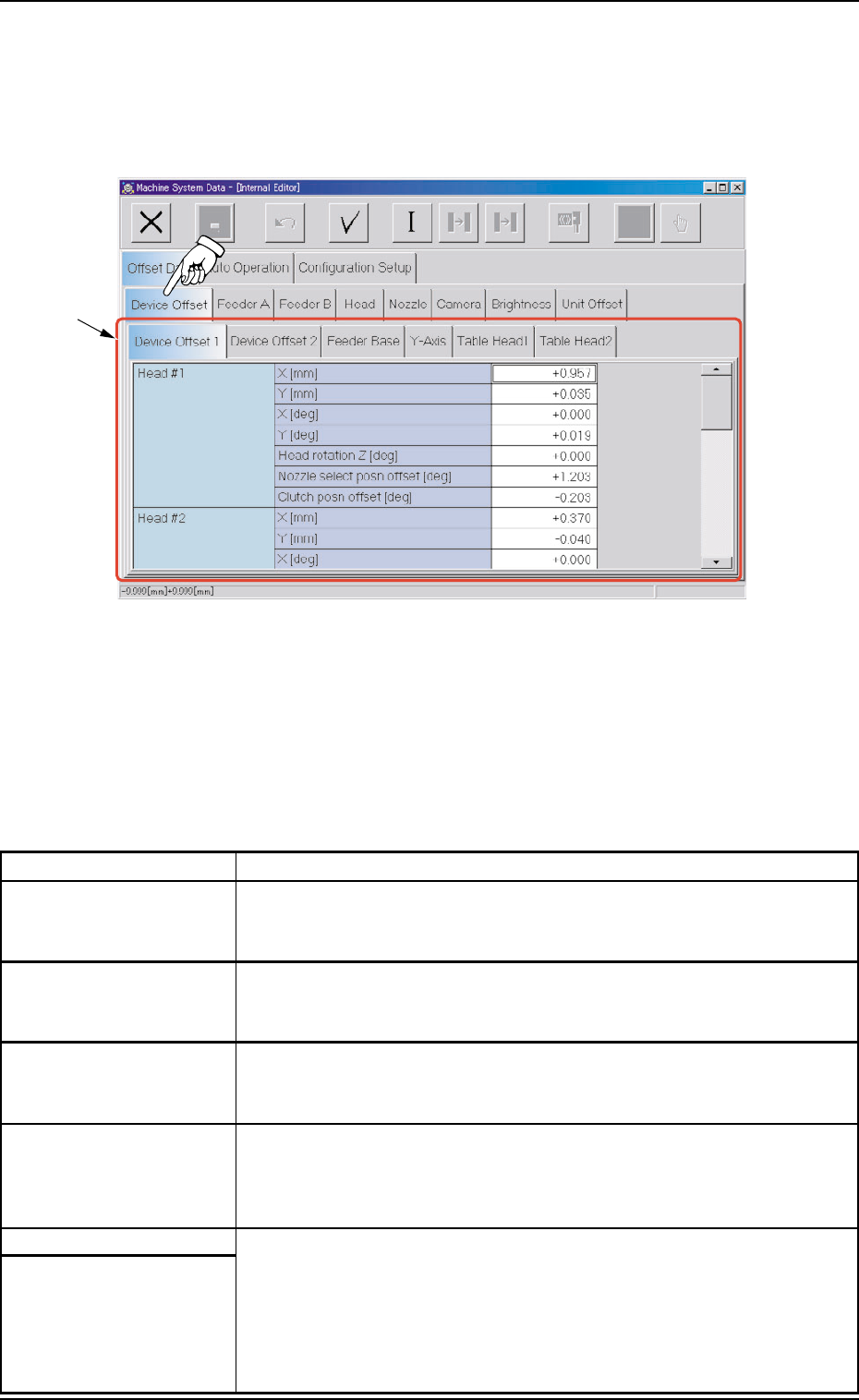
2.1.1 "Device Offset" Tab
• Sheet Layout
When the "Device Offset" tab is pressed in the "Offset Data" tab
sheet, the following tab sheet appears.
Fig. 3E5 "Device Offset" Tab Sheet
• Sheet Composition
*1 Tabs and Tab Sheets
The "Device Offset" tab sheet is provided with the following 6 tab
sheets. When each tab is pressed, the corresponding tab sheet
appears.
Table 3E2-1
Tabs Description
Device Offset 1 The corresponding tab sheet enables the operator to set the offset
data for Heads #1 and #2, the support up/down plate, the conveyor
width, the pilot driven pin, and the teaching plate.
Device Offset 2 The corresponding tab sheet enables the operator to set the offsets
for the origin position and rotational axes of the up/down shafts of
Nozzles #1 through #6 on Heads #1 and #2.
Feeder Base The corresponding tab sheet enables the operator to set the offset
data for the adjustment of the positional deviations compared with the
design dimensions of Feeder Bases #1, #3, and #4.
Y-Axis The corresponding tab sheet enables the operator to set the offset
data for the adjustment of the parallelism between the P.C.B. posi-
tioning chute and the beam (X1 and X2 axes) when the Y axis is ze-
roed.
Table Head1 The corresponding tab sheet enables the operator to set the devia-
Table Head2 tions (based on the specified distance) that are caused when Head
#1 or #2 has moved to each grid (specified distance) from the P.C.B.
positioning reference.
The "Table Head1" and "Table Head2" tab sheets look almost similar
to each other and almost the same navigations can be undertaken.
*1
2.1 "Offset Data" Tab
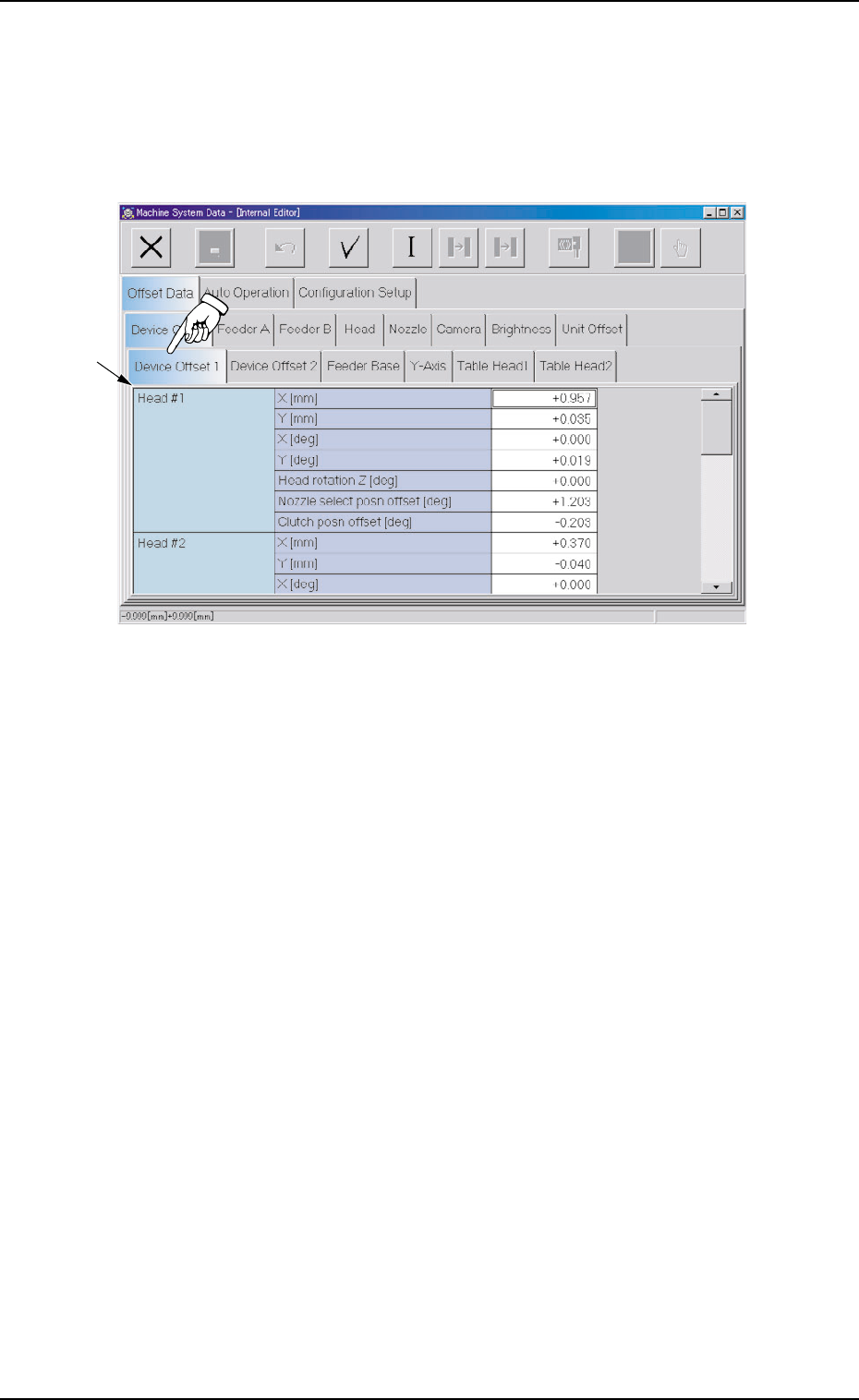
2.1.1.1 "Device Offset 1" Tab
• Sheet Layout
When the "Device Offset 1" tab is pressed in the "Device Offset" tab
sheet, the following tab sheet appears.
Fig. 3E6 "Device Offset 1" Tab Sheet
• Sheet Composition
*1 Offset Items
Set the following offset values.
Head #1 (X mm (Horizontal), Y mm (Vertical), X [deg], and Y
[deg])
The set offset parameters are used to adjust the positional and an-
gular deviations compared with the design dimensions represent-
ing the beam driving X/Y coordinates (Head Origin: H0) viewed from
the P.C.B. positioning X/Y coordinates (PL-XY: P.C.B. Origin P0).
*1
0308-004 5-9 AHB01EDTP
2.1 "Offset Data" Tab