3OM-1075-002.pdf - 第35页
(A01_05) Pre-Placed component thickness P .C.B. top [mm] When some components are placed previously on a P .C.B. by the input machine, etc., and transferred to the main ma- chine, be sure to enter the thickness of the ta…
(A01_04) P.C.B. height offset [mm]
Set an offset value as a nozzle descending distance based
on the upper surface reference of the P.C.B. in the compo-
nent placement section.
This offset value applies to all components in the pattern
program.
Unit: mm
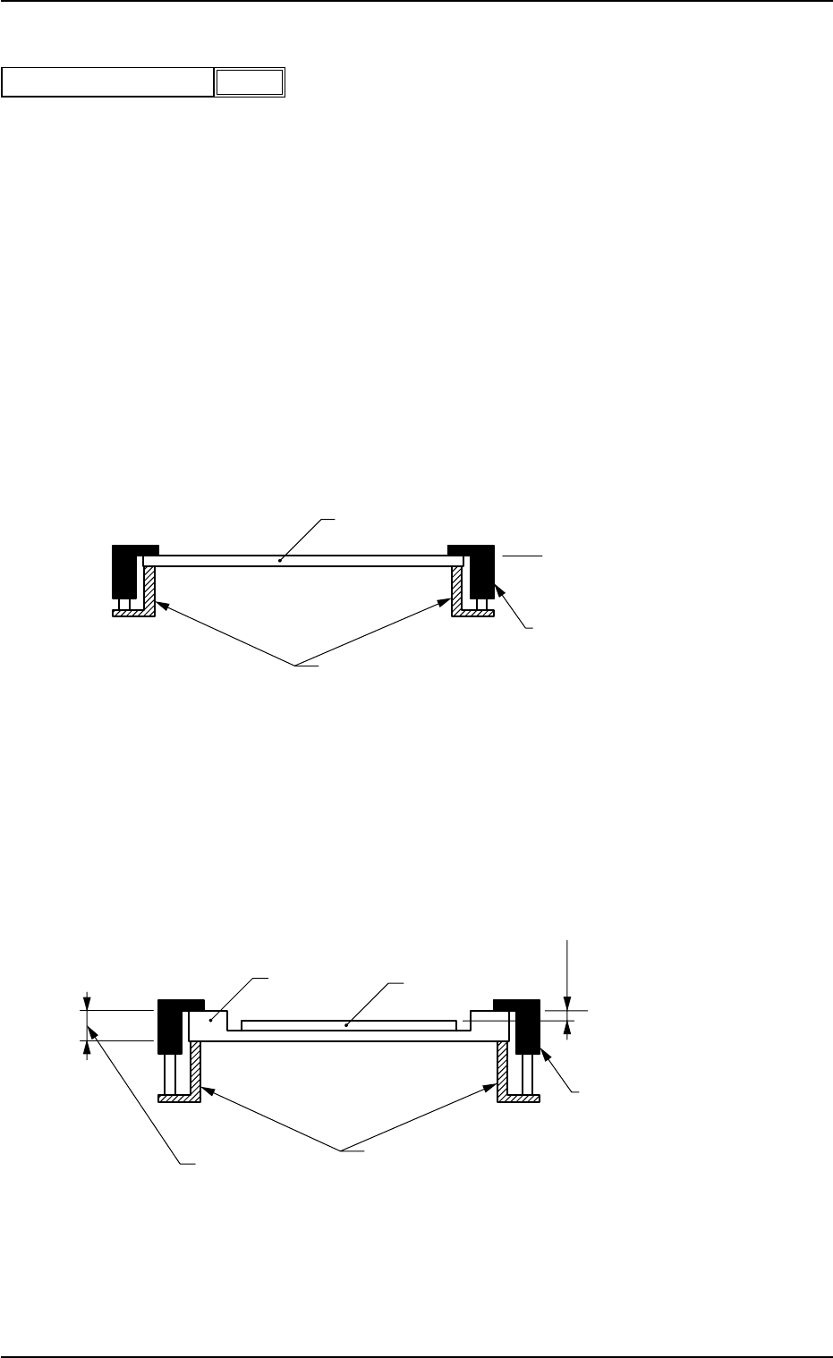
Normal Cases
Set "0.00 mm" (zero) in the text box.
The figure below shows that the upper surface of a P.C.B. is
maintained by the P.C.B. support pins at the P.C.B. upper
surface reference.
Fig. 3B17
Example of Jig P.C.B. Usage
The figure below shows that the upper surface of a P.C.B. is
lower than the P.C.B. upper surface reference.
If "+a mm" is set as an offset value at this time, components
can be placed correctly on the P.C.B.
Fig. 3B18
Data Input Range
-9.99 to +9.99
0206-002 2-15
AHB01EDTP
2.3 Operation Data
+0.00P.C.B. height offset
[mm]
Fig. 3B16
a mm
Clamp Plates
T (Thickness)
Chute
P.C.B. Upper Surface
Reference
P.C.B.
Jig P.C.B.
Clamp Plates
Chute
P.C.B. Upper Surface
Reference
P.C.B.
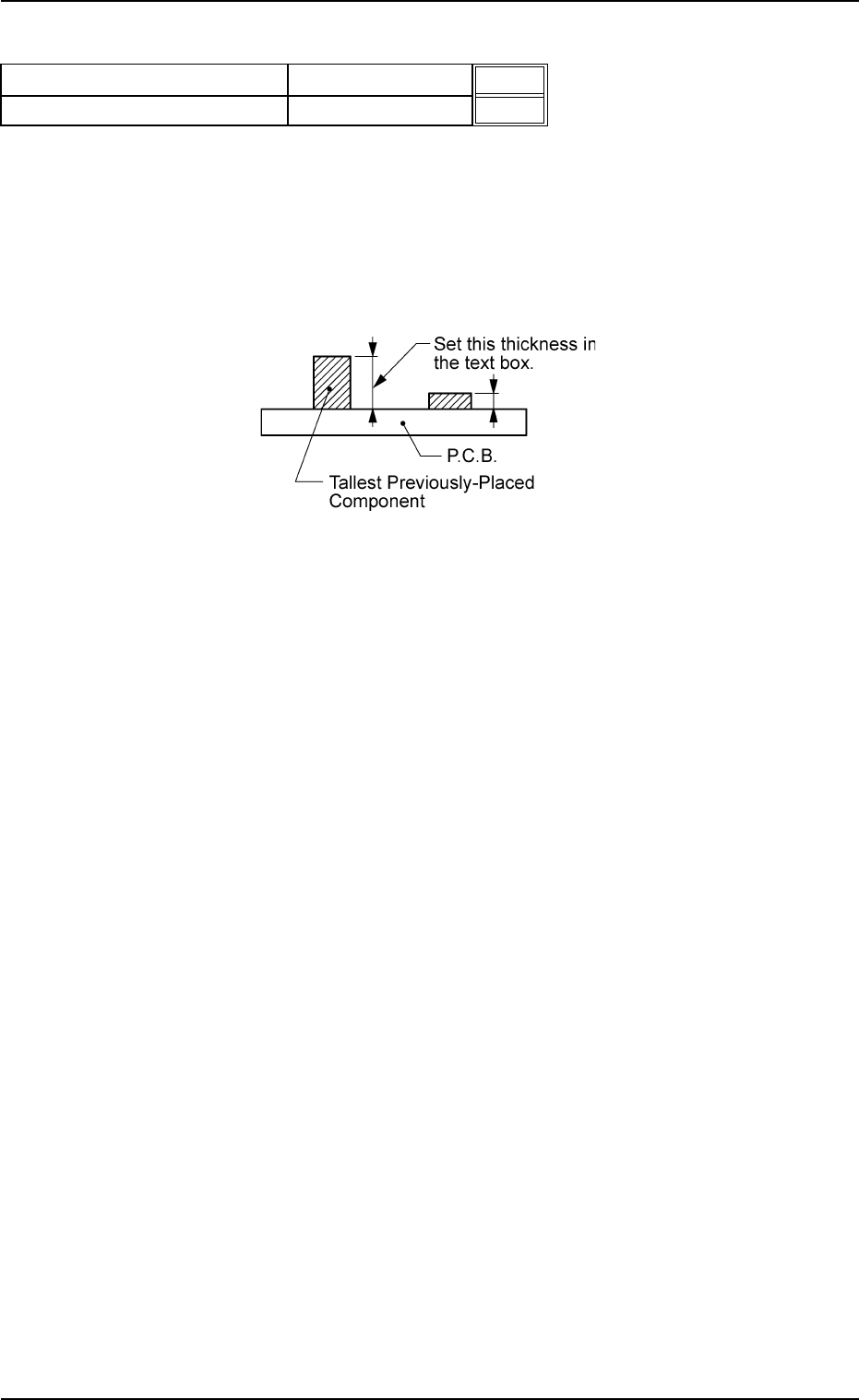
(A01_05) Pre-Placed component thickness
P.C.B. top [mm]
When some components are placed previously on a P.C.B.
by the input machine, etc., and transferred to the main ma-
chine, be sure to enter the thickness of the tallest compo-
nent of all in the text box.
Unit: mm
Fig. 3B20
Data Input Range: 0 to 20.00
Pre-Placed component thickness
Fig. 3B19
20.00
30.00
0206-002 2-16 AHB01EDTP
2.3 Operation Data
P.C.B. top [mm]
P.C.B. bottom [mm]
(a) When components are not placed previously, set "00.00"
(zero) in the text box.
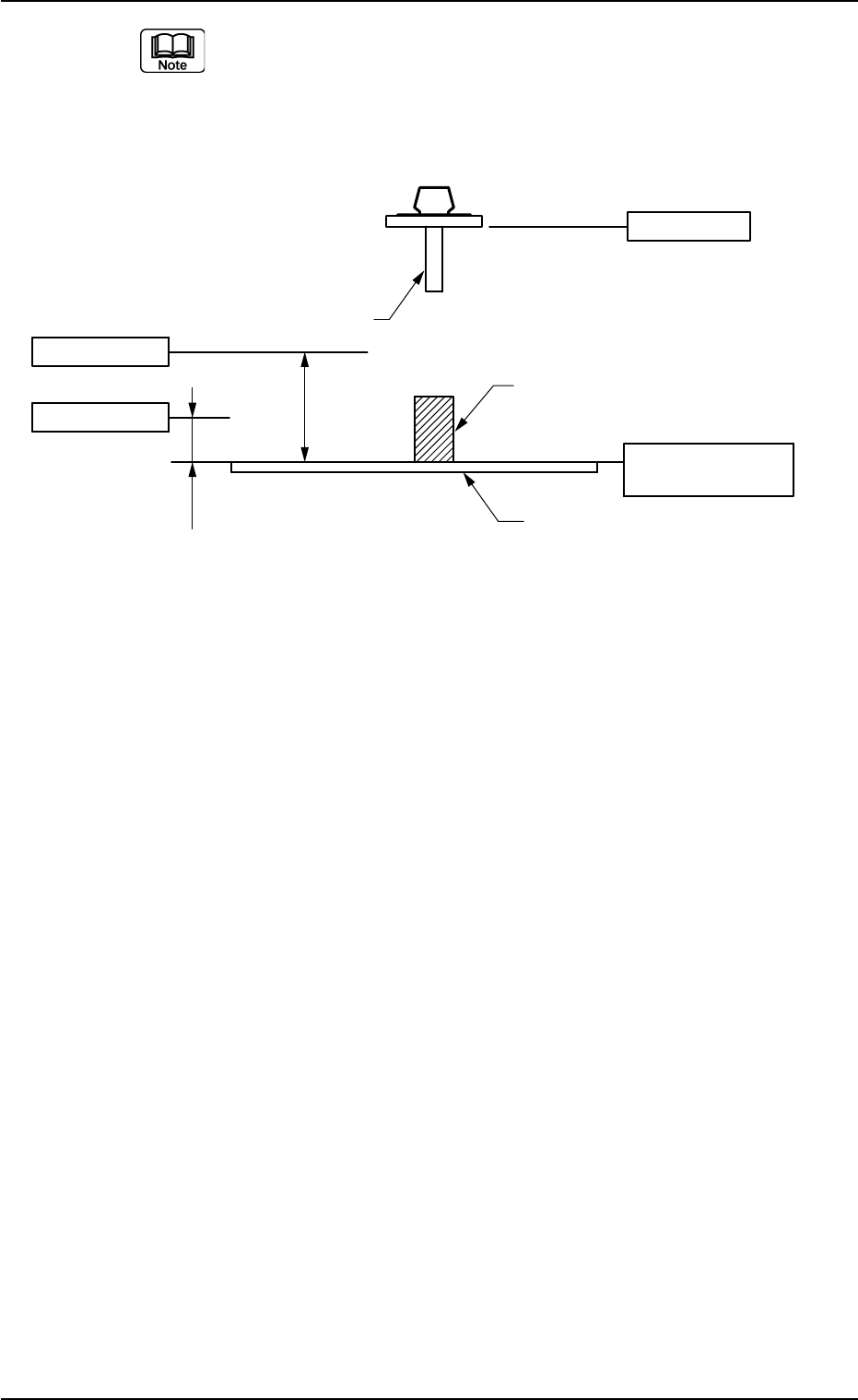
(b) Lower and Upper Pass Lines
Fig. 3B21
Lower Pass Line:
This line is the lowest line for the X/Y beam movement
when the thickness of a previously-placed component (al-
ready-placed component) is 6.5 mm or less.
When this level is not maintained, a physical interference
with a structure occurs.
This level is also regarded as a focus level for compo-
nent recognition.
As no height regulation is made for the previously-placed
components (already-placed components) during the X/
Y beam movement (component picks, component rec-
ognition, component discharge operation, etc.) outside
the P.C.B. area (outside the area where a P.C.B. is lo-
cated for component placement), the X/Y beam moves,
keeping the lower ends of the nozzles (without picked
components) and the lowest ends of the picked compo-
nents in this level.
0206-002 2-17
AHB01EDTP
2.3 Operation Data
8.5mm
(Design Dimension)
22mm
(Design
Dimension)
L-Axis Origin
Nozzle
Upper Pass Line
Lower Pass Line
P. C. B .
P.C.B. Upper Surface
Reference
Previously-Placed Component
(including the already-placed component)