3OM-1075-002.pdf - 第65页
2 . 5 Placement Data Fig. 3B88 Edit Window (Example) (C01) Placement Data Un (C01_01) Selection of Placement Data Group Select one of the following tabs (placement data groups) in one pattern program. U01 : First Placeme…
2.4 Placement Feeder Location Data
0308-003 2-45 AHB01EDTP
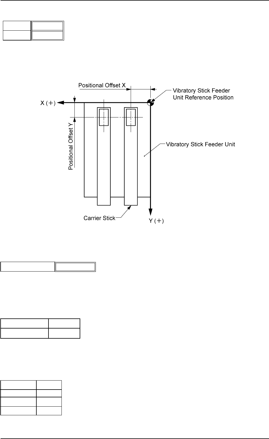
(B02_07) Position X [mm], Y [mm]
Enter the distances between the reference position of the
vibratory stick feeder unit and the pick-up position.
Unit: mm
Data Input Range
X: 0.4 to 120.0 Y: 0.4 to 50.0
Fig. 3B85
(B02_08) Library Comment
Displayed is the comment entered in the component library
data.
(B02_09) Dir [deg], Carrier Data Type
Shown are the values specified in the component library data.
(B02_10) Nozzle #1, C, Nozzle #2, C
Displayed are the nozzle IDs and control commands speci-
fied in the component library data.
X [mm]
Fig. 3B84
Y [mm]
000.00
000.00
Fig. 3B85-1
Library Comment
Fig. 3B86
Carrier Data Type
Dir [deg]
0
Vib Stick
EA06
S
EA04
-
Nozzle #1
C
Nozzle #2
C
Fig. 3B87
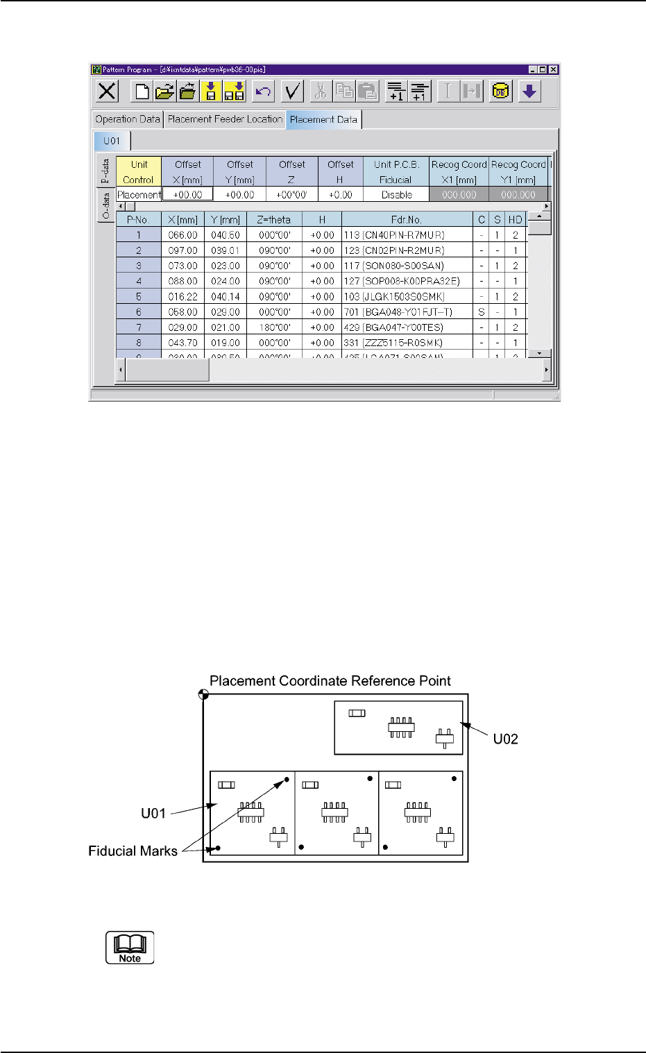
2.5 Placement Data
Fig. 3B88 Edit Window (Example)
(C01) Placement Data Un
(C01_01) Selection of Placement Data Group
Select one of the following tabs (placement data groups) in
one pattern program.
U01 : First Placement Data Group
U02 : Second Placement Data Group
È
Un : Up to 99 placement data groups can be specified.
Fig. 3B89 Example of Placement Data (TIM-X100R)
(a) "U01" is used in normal cases.
(b) The operation and feeder location data are used commonly.
(c) Refer to "2.1 Types of P.C.B.’s and Required Data" and "3.
Example of Pattern Program Creation" for details.
0206-002 2-46 AHB01EDTP
2.5 Placement Data
(C02) Placement Data (P)
(C02_01) Unit Control
Select one of the following options to determine whether the
selected placement data (U01, U02, ..... Un) should be used.
In normal cases, select "Placement".
Placement : The placement data of the selected unit
(group) becomes valid.
Bypass : The placement data of the selected unit
(group) becomes invalid.
Offset X [mm], Offset Y [mm]
Set the offset values for all placement coordinates X and Y,
the unit P.C.B. recognition coordinates, and the local P.C.B.
recognition coordinates in the placement data (P-data).
Unit: mm
Data Input Range
X: -99.99 to +99.99 Y: -99.99 to +99.99
(a) Use "00.00" (zero) in normal cases.
(b) Note that these offset values do not give any effect to the
coordinates (X [mm] and Y [mm]) of "A02_02 P.E.C. rec-
ognition mode Global".
Offset Z
Set the offset value for all placement angles (Z=Theta) in
the placement data (P-data).
Data Input Range
-99.99 to +99.99
Use "00°00′" (zero) in normal cases.
Offset H
Set the offset value for all placement height "H" in the place-
ment data (P-data).
Data Input Range
-9.99 to +9.99
Use "0.00" (zero) in normal cases.
0206-002 2-47
AHB01EDTP
2.5 Placement Data
Fig. 3B90
Placement
Unit Control
Offset X [mm]
Fig. 3B91
Offset Y [mm]
+00.00
+00.00
Offset Z
Fig. 3B92
+00°00′
Offset H
Fig. 3B93
+0.00