3OM-1075-002.pdf - 第58页
(B01_01) Fdr . No. Shown are the feeder Nos. in the placement feeder location data. The numbers in ( ) indicate the feeder Nos. that will actually be loaded with components. Data Input Range Feeder Base #1: 101 to 132 Fe…
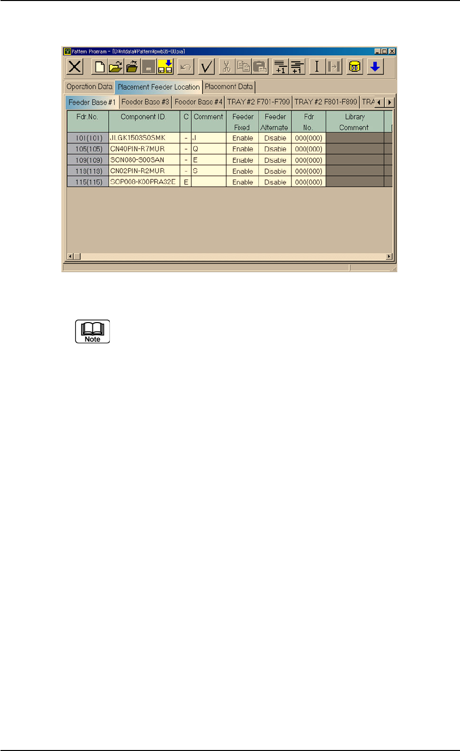
Fig. 3B64 Edit Window (Provided with Multi-Layer Tray Feeder 2)
The "TRAY #2 F701-F799", "TRAY #2 F801-F899", and "TRAY
#2 STEP" tabs are provided for the options.
The tab sheet may look different, depending on which options
are selected.
2.4 Placement Feeder Location Data
0308-003 2-38 AHB01EDTP
(B01_01) Fdr. No.
Shown are the feeder Nos. in the placement feeder location
data.
The numbers in ( ) indicate the feeder Nos. that will actually
be loaded with components.
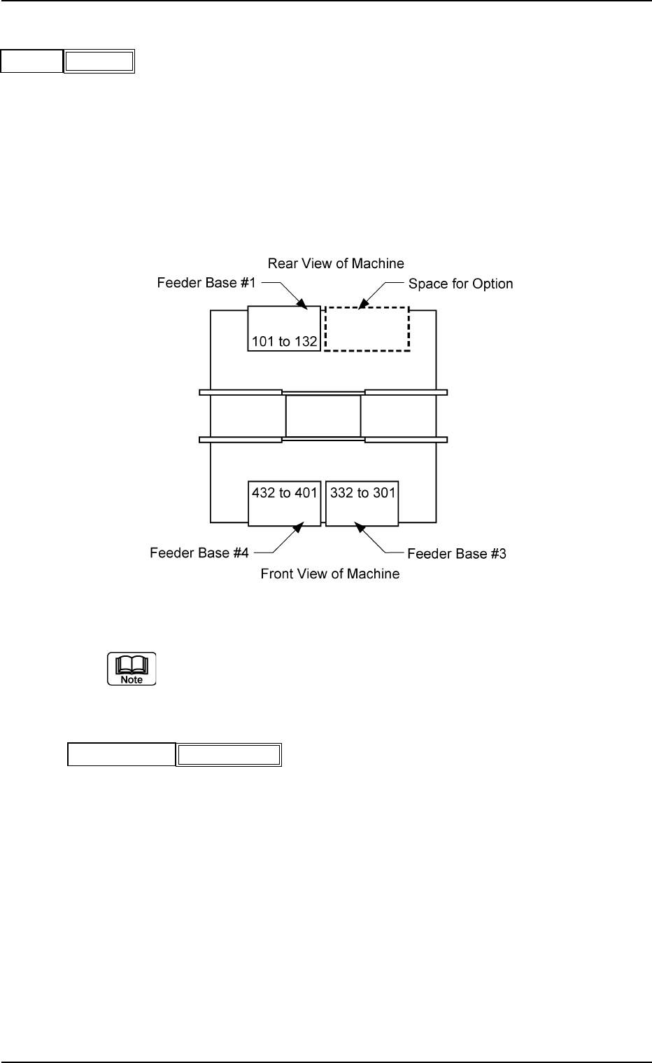
Data Input Range
Feeder Base #1: 101 to 132
Feeder Base #3: 301 to 332
Feeder Base #4: 401 to 432
Fig. 3B66
The feeder Nos. (Fig. 3B64) in ( ) indicate the numbers where
the feeder No. offset in the operation data is added.
(B01_02) Component ID.
Set component IDs in the text boxes.
0206-003 2-39 AHB01EDTP
2.4 Placement Feeder Location Data
Fdr.No.
Fig. 3B65
101(101)
Fig. 3B67
Component ID.
C1005T05B0---
(B01_03) C
Set control commands in the text boxes.
- (hyphen): This command handles the steps as those
for the placement feeder location data.
E: This command shows the end of the placement
feeder location data.
The step where "E" is set is valid.
S: This command invalidates the steps specified as
placement feeder location data.
X: This command invalidates the steps specified as
placement feeder location data and shows the end
of the data.
(B01_04) Comment
A comment can be entered for each feeder No. (Fdr. No.).
Up to 32 characters (alphanumerics and marks) can be
used.
(a) The performance of the machine is not affected by these
commands. In other words, it has nothing to do with or
without these comments.
(b) It is recommended to set helpful information on comments
related to the feeder Nos. (Fdr. Nos.).
(B01_05) Feeder Fixed
Select "Enable" or "Disable" to determine whether or not the
feeder positions should be fixed in place.
When "Enable" is selected, the feeder No. (Fdr. No.) and
the component ID are not affected by any insert and delete
operations of a component.
Disable: The feeder position is not fixed.
Enable: The feeder position is fixed.
(B01_06) Feeder Alternate
Select "Enable" or "Disable" to determine whether or not the
feeder alternate function should be used.
Disable : The feeder alternate function is not used.
Enable : The feeder alternate function is used.
0308-003 2-40
AHB01EDTP
2.4 Placement Feeder Location Data
Fig. 3B68
C
-
Fig. 3B69
Comment
Fig. 3B71
Feeder Alternate
Disable
Fig. 3B70
Feeder Fixed
Disable
If a control command other than the following ones is
used, the step becomes invalid.
CAUTION