3OM-1075-002.pdf - 第125页
Fig. 3B172 4.3 "Placement Feeder Location" T ab [VIB. STK. UNIT] Icon 0308-001 2-105-1 AHB01EDTP
0308-002 2-105 AHB01EDTP
4.3 "Placement Feeder Location" Tab
• Operation Procedure
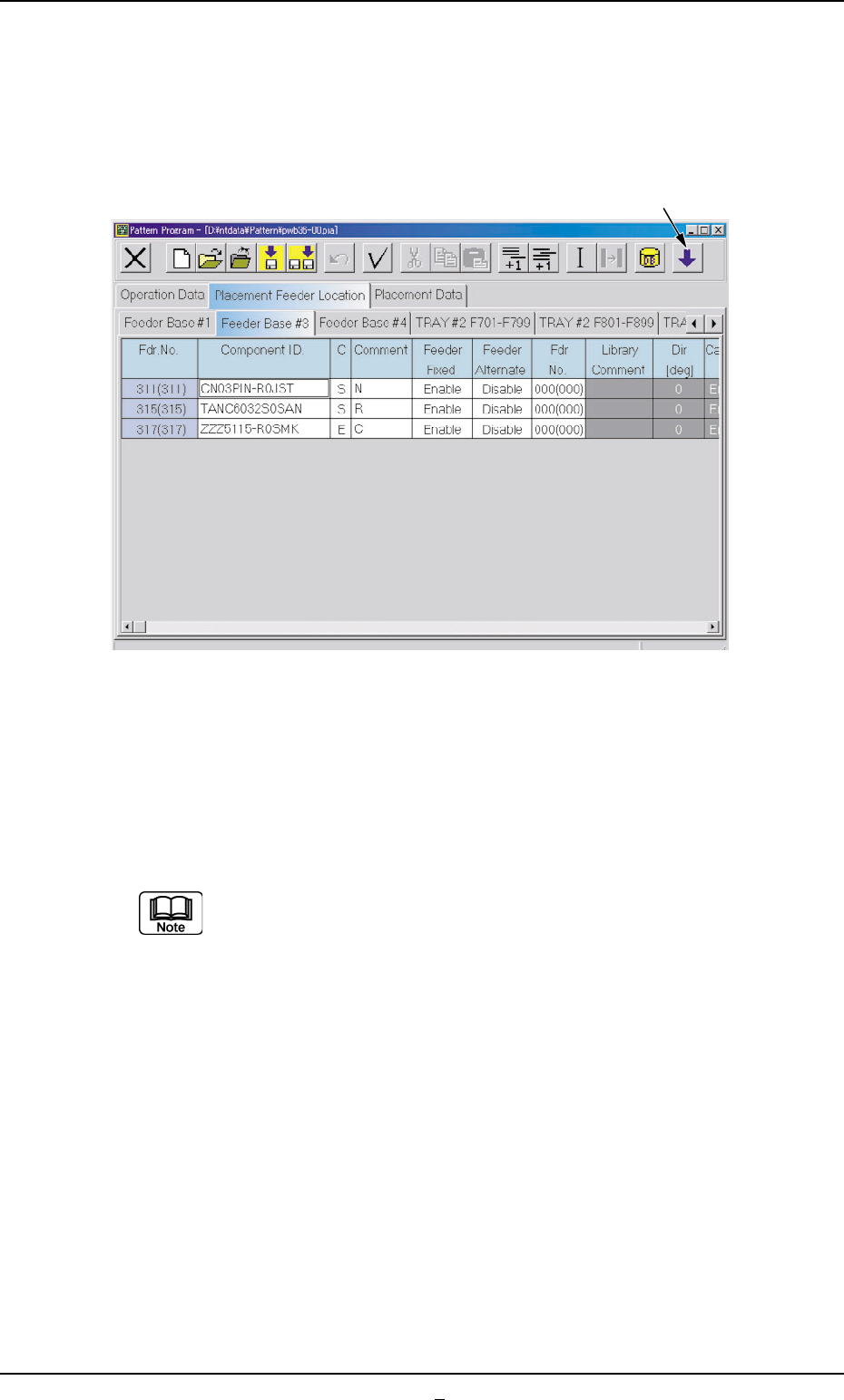
(1) Select the tab corresponding to the feeder base where the vibratory
stick feeders should be allocated.
The vibratory stick feeders can be allocated to Feeder Base #3 or
#4.
Fig. 3B171
(2) Press the [Open 2nd. Toolbar] icon.
(3) Select the feeder No. (Fdr. No.) where the vibratory stick unit should
be allocated and press the [VIB. STK. UNIT] icon.
"<VIB.STK.UNIT>" appears in the "Component ID." text box of the
reference feeder No. (Fdr. No.).
(a) In the case of a feeder No. (Fdr. No.) where no vibratory
stick unit can be allocated, "The number of feeders has
reached the maximum counts." appears in the corre-
sponding text box.
(b) Up to 3 vibratory feeders can be installed on one feeder
base.
[Open 2nd. Toolbar] Icon
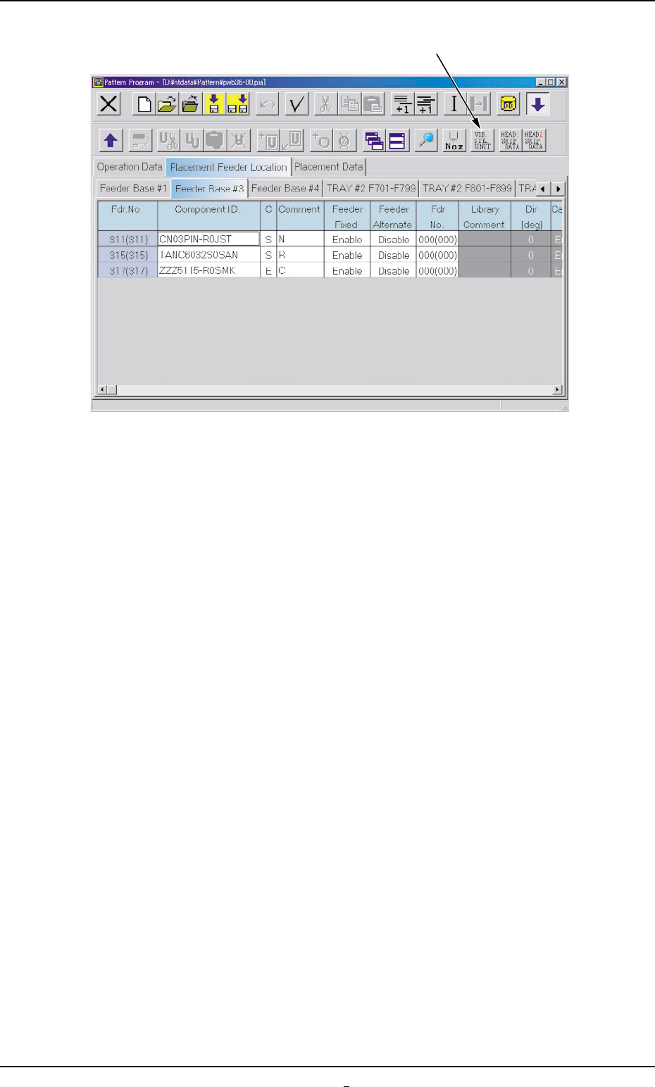
Fig. 3B172
4.3 "Placement Feeder Location" Tab
[VIB. STK. UNIT] Icon
0308-001 2-105-1 AHB01EDTP
0206-001 2-106 AHB01EDTP
4.3 "Placement Feeder Location" Tab
Fig. 3B173
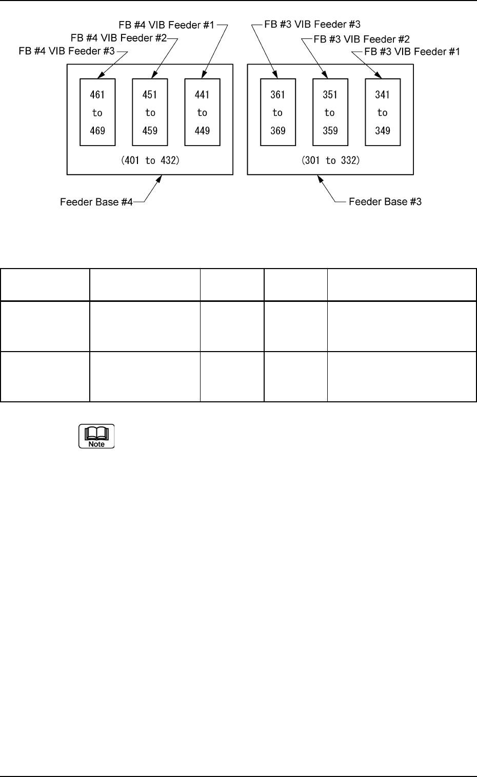
Table 3B35
Feeder Base No. Unit No. Reference Exclusive Carrier Stick Fdr. No.
Fdr. No. Fdr. No.
FB #3 VIB Feeder #1 303 301 to 310 341 to 349
Feeder Base #3 FB #3 VIB Feeder #2 315 311 to 322 351 to 359
FB #3 VIB Feeder #3 327 323 to 332 361 to 369
FB #4 VIB Feeder #1 403 401 to 410 441 to 449
Feeder Base #4 FB #4 VIB Feeder #2 415 411 to 422 451 to 459
FB #4 VIB Feeder #3 427 423 to 432 461 to 469
(a) The reference feeder Nos. (Fdr. No.) are automatically allo-
cated when the vibratory stick feeders are specified.
(b) The exclusive feeder Nos. (Fdr. Nos.) indicate the ranges
occupied exclusively on the feeder base.
No tape feeder can be allocated to this feeder No. (Fdr. No.).