operation-cp45.pdf - 第103页
Sensor Detection Functions 4-1 Chapter 4. Sensor Detection Functions 4.1. Door Switch Door switches for detecting the opening/closing stat us of the front and rear doors are attached to this equipment respectively. The d…
Samsung Component Placer CP-45F(V)/FS Operations Manual
3-12
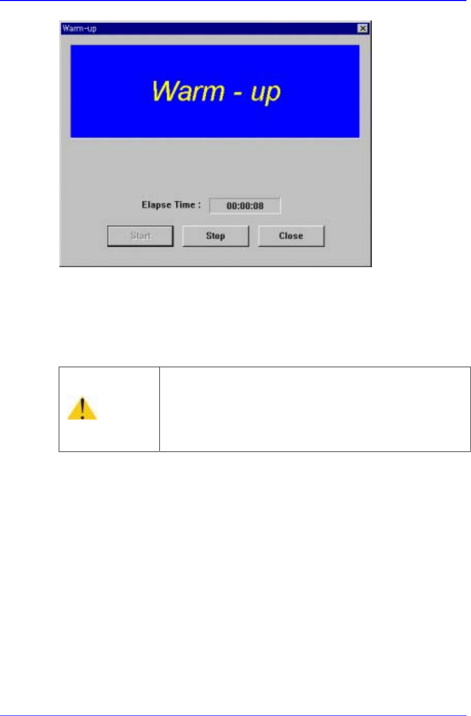
Figure 3-5. “Warming Up” dialog box 2
3. Perform preparatory operation for about 10 minutes, then click on the <Stop> button
in the dialog box. The preparatory operation is terminated, and the system returns to
the standby status.
Warning
Adjusting the sensor or correcting an error while the
machine is ready could result in personal injury.
Be sure to adjust the sensor or correct an error in the stop
status after canceling the ready status.
Sensor Detection Functions
4-1
Chapter 4. Sensor Detection Functions
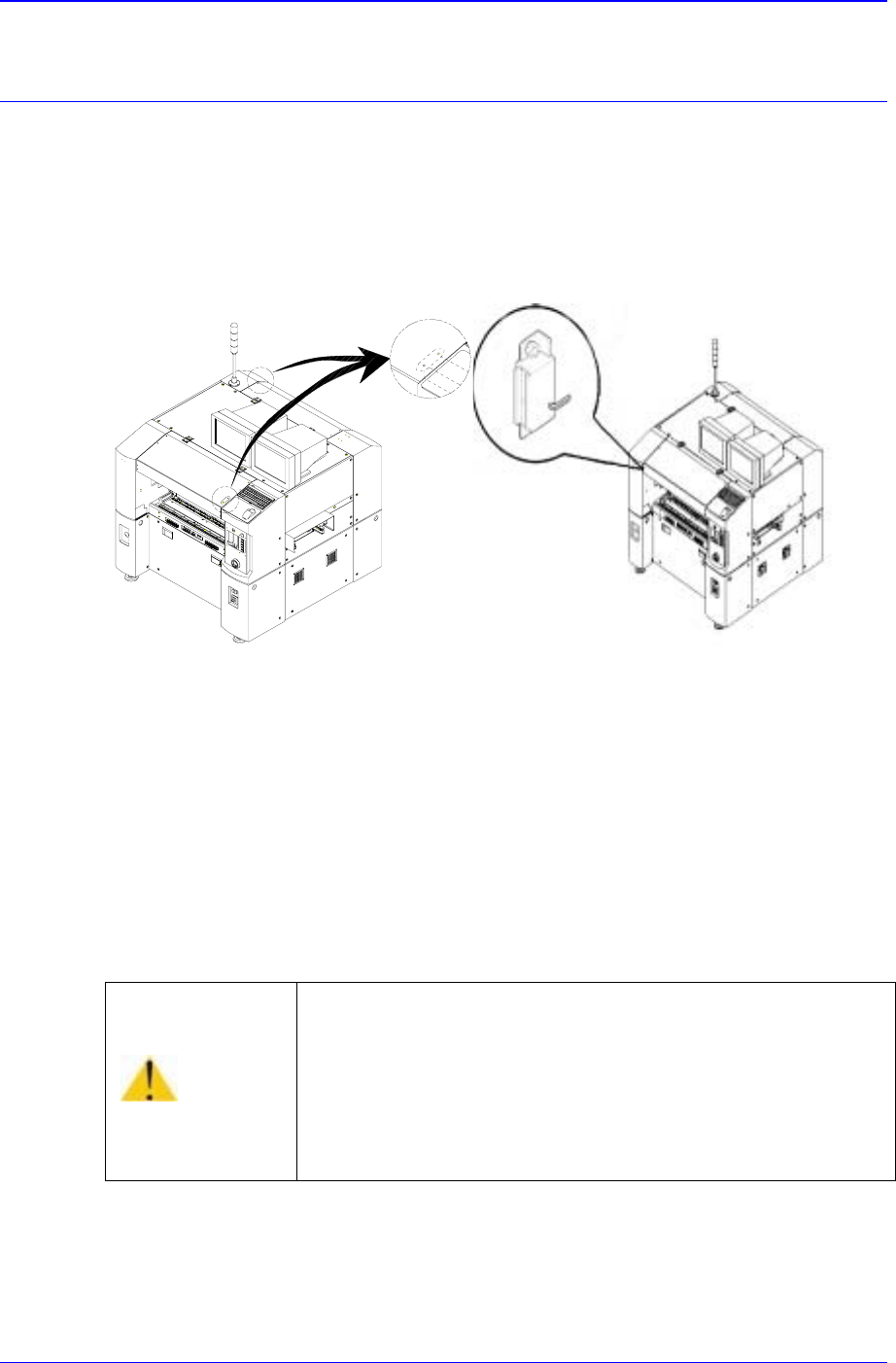
4.1. Door Switch
Door switches for detecting the opening/closing status of the front and rear doors are
attached to this equipment respectively. The door switch is integrated with a magnet and a
door opening/closing sensor.
(CE Option) (Normal)
Figure 4-1. Door Switch
If the door is open while this equipment is running, the door switch is activated and the
system comes into the emergency stop status. The emergency stop status is released if the
door is closed. In order to resume the operation, press <Stop> and <Reset> switch on the
operation panel to release the emergency status, then press <Main Start> and <Ready>
switch.
Warning
If the safety sensor of the door is cancelled arbitrarily, the
machine will not stop even though the door is opened during
operation, which could cause injury.
The safety sensor of the door must not be cancelled
arbitrarily.
Samsung Component Placer CP-45F(V)/FS Operations Manual
4-2
4.2. Feeder Unlock Sensor
Feeder unlock sensors are installed at the front and rear of this equipment. The system
comes into the emergency stop status if the feeder is not installed correctly at the feeder
base. In this case, verify that the feeder is installed properly.
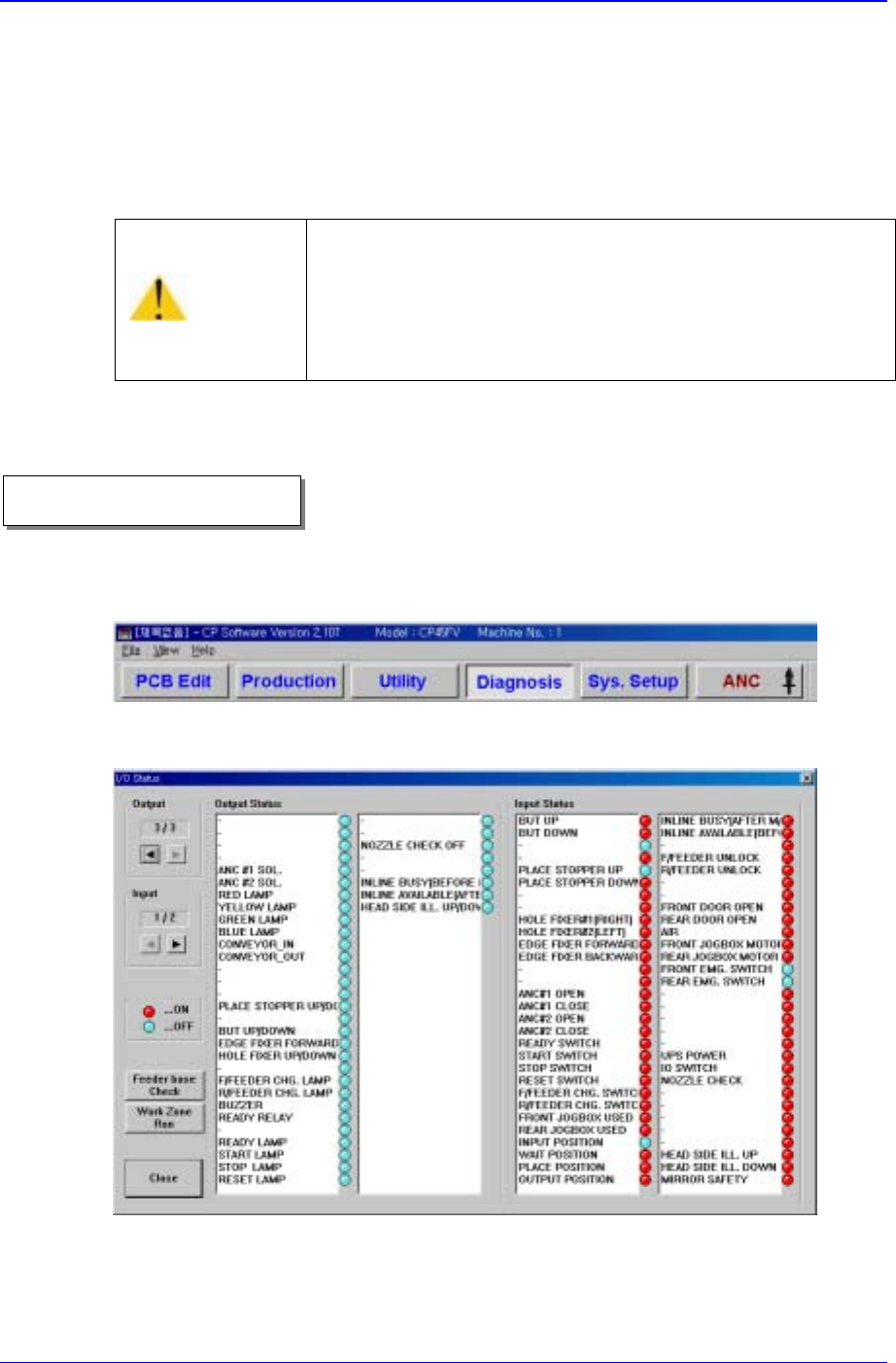
4.3. Up/Down of Backup Table
1. Select <Diagnosis> from the MMI main menu tool-bar, and select “<I/O>(F2)” from
the sub menu tool-bar on the left displayed.
“I/O Status” dialog box is shown on the screen.
Figure 4-2. “Manual Control” dialog box
2. In order to move the back-up table, double-click on the <But Up/Down> in the
<Output> list box, or click on the adjacent round button.
Caution
If the feeder loose sensor is cancelled arbitrarily, the head
and the feeder might collide as a loose feeder cannot be
sensed.
Do not cancel the feeder loose sensor arbitrarily.
Operational procedure