operation-cp45.pdf - 第280页
Samsung Component Placer CP-45F(V)/FS Operations Manual 14-6 <Outer>: Set the light value for the outer light. The range of possible light values is 0 – 15. <Inner>: Set the light value for the inner light. T…
Diagnosis Command
14-5
<Upward> Camera
Select the fix camera. The fix camera is also called upward camera. Up to 3 fix
cameras can be installed.
<Head Fly> Camera
Select the fly camera. The CP45FV model has 6 fly cameras.
<Light Value> group
Set the light value.
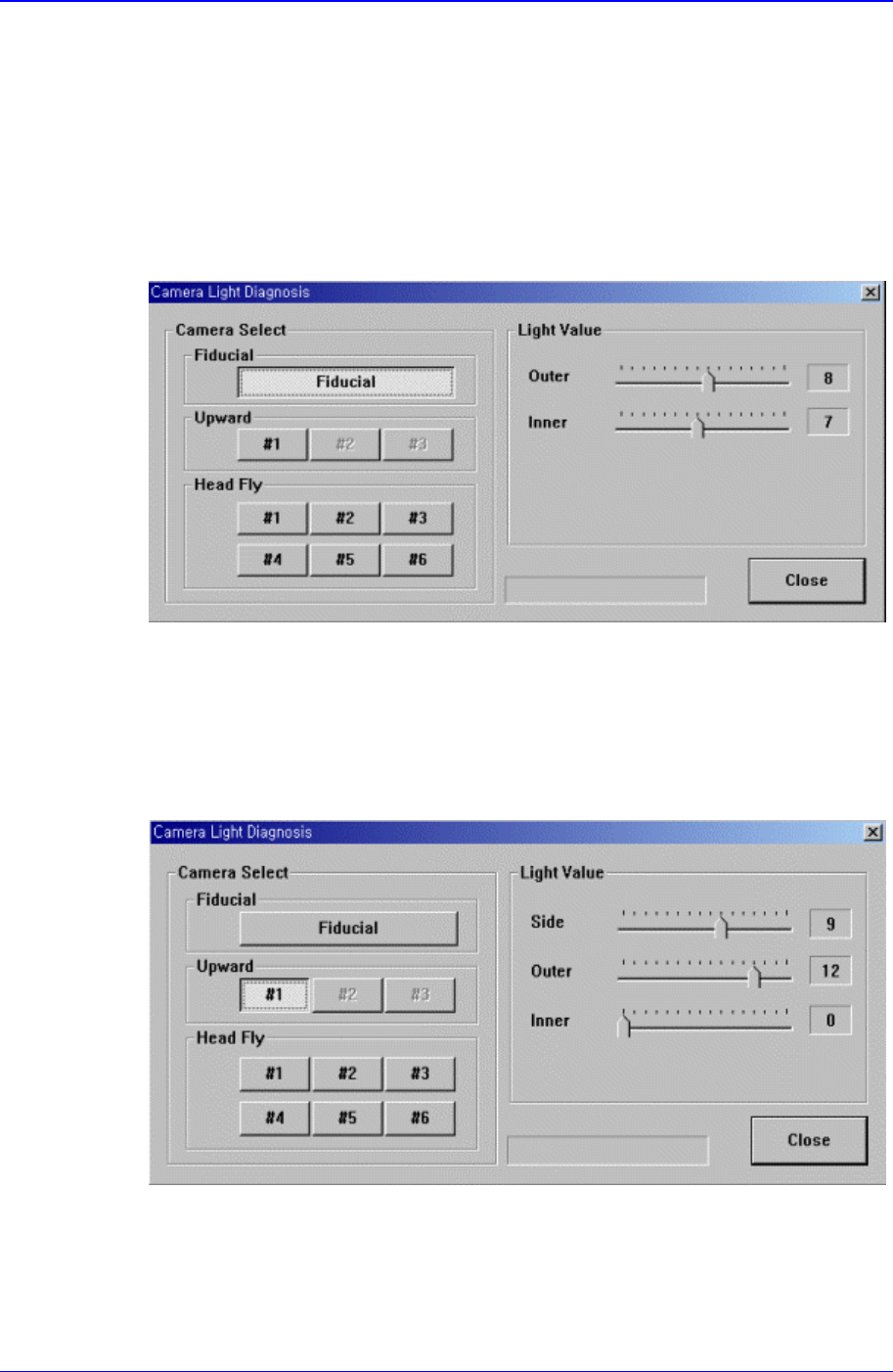
When the fiducial camera is selected, the following screen is displayed.
Figure 14-6. When the fiducial camera is selected in “Diagnosis : Camera Light
Diagnosis”
The range of possible light values is 0 – 15.
When the upward camera is selected, the following screen is displayed.
Figure 14-7. When the Upward Camera is selected in “Diagnosis : Camera Light Diagnosis”
<Side>: Set the light value for the side light. The range of possible light values is 0 –
15.
Samsung Component Placer CP-45F(V)/FS Operations Manual
14-6
<Outer>: Set the light value for the outer light. The range of possible light values is 0
– 15.
<Inner>: Set the light value for the inner light. The range of possible light values is 0
– 15.
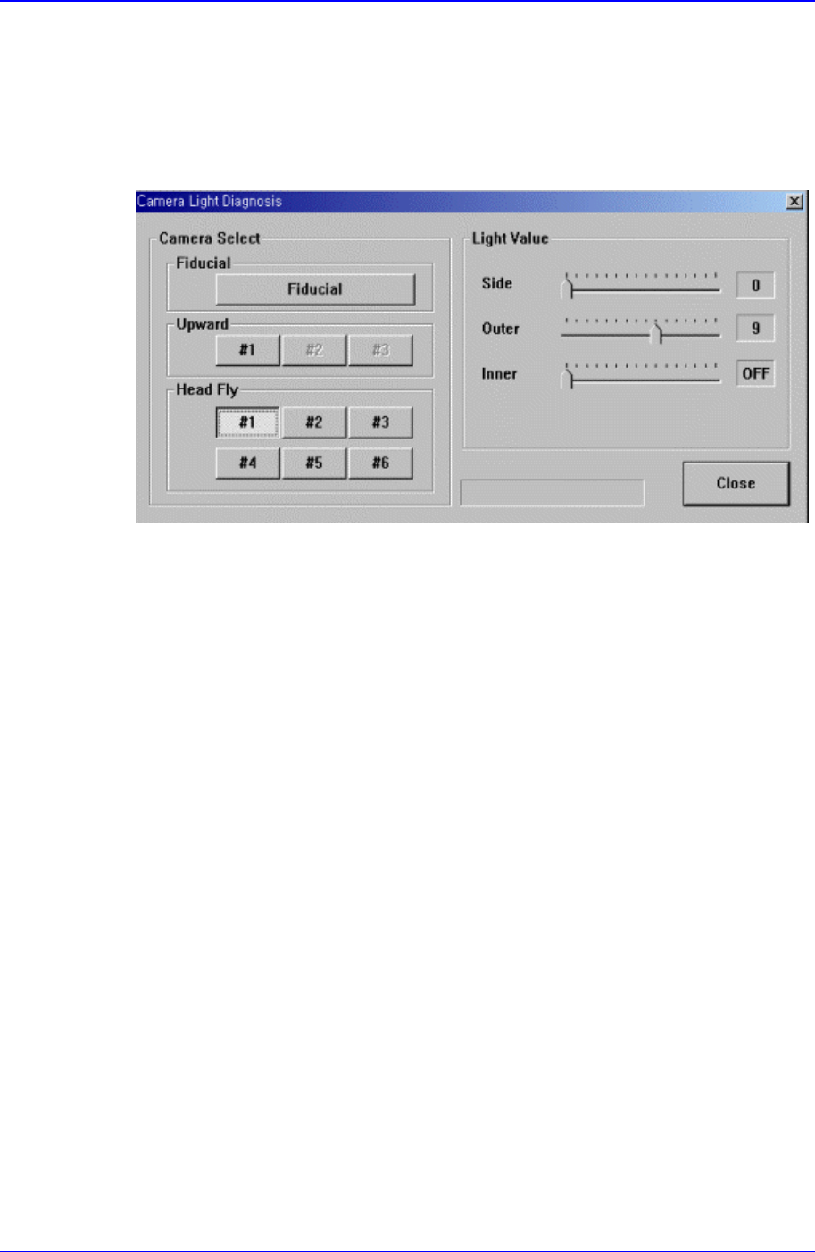
When the head fly camera is selected, the following screen is displayed.
Figure 14-8. When the Head Fly Camera is selected in “Diagnosis : Camera Light Diagnosis”
<Side>: Set the light value for the side light. The range of possible light values is 0 –
15.
<Outer>: Set the light value for the outer light. The range of possible light values is 0
– 15.
<Inner>: Set the light value for the inner light. ON or OFF is possible.
<Close> button
Closes the dialog box.
14.4. Vacuum [F5]
Checks the air pressure status of the head.
When this button is clicked on, the following dialog box is displayed.
Diagnosis Command
14-7
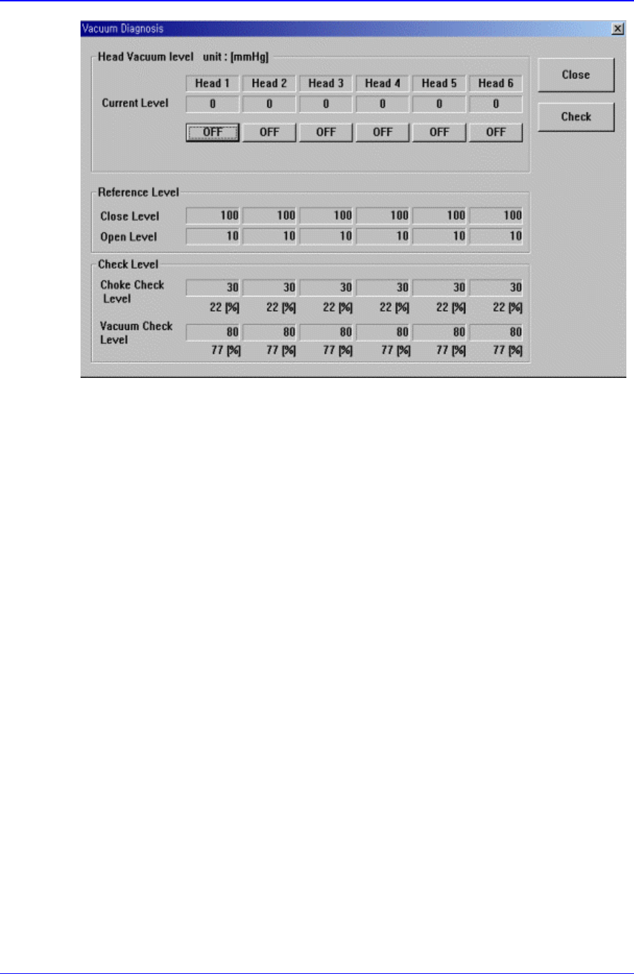
Figure 14-9. “Diagnosis : Vacuum Diagnosis” dialog box
<Head Vacuum level> group
Displays the vacuum level of each head and controls the vacuum generator.
<Current Level>
Displays the current vacuum level of each head.
<OFF> button
Controls the vacuum generator of each head.
When “OFF” is displayed, pressing this button turns off the vacuum generator
and displays “ON” on the button. When “ON” is displayed, pressing this button
turns on the vacuum generator and displays “OFF” on the button.
<Reference Level> group
When the vacuum level is used as a criteria for determining component pickups by
each head, displays the standard value.
<Close Level>
Display the vacuum level of each head when the nozzle is stuck fast to the Check
PAD.
<Open Level>
Displays the vacuum level of each head when the nozzle is open.
<Check Level > group
Displays the vacuum level that is used as a criteria for determining component
pickups.
<Choke Check Level>
Displays the vacuum level that considers the nozzle to be choked up before
component pickups.
<Vacuum Check Level>
Displays the vacuum level that considers a pickups to be successful after