operation-cp45.pdf - 第122页
Samsung Component Placer CP-45F(V)/FS Operations Manual 6-4 Fixing of the board should be done accura tely as the sensor dog for detecting the location of a hole fixer pin may not be detected, if the position of the ho…

Preparation for Production
6-3
Caution
Unscrew one socket set screw of no.1 in the figure above
and adjust the position
As the 4 socket head cap screws of no. 2 are used to fix the
hole fixer on the conveyor, the hole fixer can not be fixed if
they are unscrewed.
They must not be unscrewed.

Samsung Component Placer CP-45F(V)/FS Operations Manual
6-4
Fixing of the board should be done accurately as the sensor dog for detecting the
location of a hole fixer pin may not be detected, if the position of the hole fixer pin
for fixing the board is not proper or the sizes of the hole and the pin do not match.
Figure 6-3. Position of Hole Fixer Pin
A: If the size of the hole of the board is greater than that of the pin, the sensor
dog is positioned too high.
B: The pin is left free and fails to support the fixing hole in the board.
C: The pin and the hole in the board are properly positioned.
D: If the size of the pin is greater than that of the hole in the board, the sensor
dog is positioned too low.
E: The pin fails to support the hole in the board, but supports point on the lower
portion of the board.
All cases except for C generate errors when the equipment is operated.
P
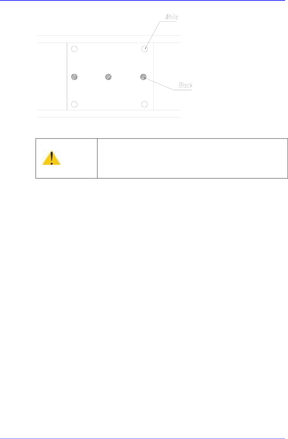
osition the back-up pins properly so that they support the lower portion of the board.
There are white and black back-up pins. It is preferable to place white back-up pins at
the corners since their spring constant is higher than that of black pins, and black pins
should be arranged along the middle of the board.
The back-up pins should be placed with the back-up table always raised in order to
prevent the collision between the pins and the board detection sensor.
Caution
If the Pin size and the hole size do not match, the board
might be bent.
Be sure to select the right size pin.
Caution
The back up pin needs to be arranged while the Back Up
Table is lifted, otherwise, it could collide with the board
detection sensor when it is arranged. Be sure to arrange the
back up pin while the back up table is lifted.
Preparation for Production
6-5
Figure 6-4. Positions of Backup Pins
Caution
If the board is mountable on double-faced, placing the back
up pin wrongly could lead to improper placement.
Be sure to adjust the Back Up Pin position correctly.