operation-cp45.pdf - 第41页
Features and Scope of Equipment 1-3 1.2. Applicable Components and Packages 1.2.1. Configuration of t he head and vision recognition system The vision recognition systems of the CP-45F/V and CP-45FS related to the comp…

Samsung Component Placer CP-45F(V)/FS Operations Manual
1-2
The head assembly contains Z-axis and θ-axis for from micro chips to large fine-
pitch components.
Designed for high stiffness, the spindle module has a part size capability that
enables faster motion time (Z-axis motion time - 9G).
Z-axis motion is driven by a AC servomotor through high-precision Timing Belt.
The moving mass of this mechanism is balanced by the constant force spring.
θ
-axis motion is carried out by high precision, zero backlash ball bearing spline
assembly and a micro-step motor.
The high-precision micro step motor controls two axes simultaneously by connecting
two ball bearing spline nut housings with the timing belt.
The X-Y axis driving gear is each driven by AC servomotor, thus securing the
precision required for high-precision feed.
A move camera enables high-speed fiducial mark recognition for high-speed
placement (the placement of components on a PCB) performance.
The software (Man-Machine Interface, MMI), based on Microsoft Window 98 has
improved the ease of use. For operating equipment, and for creating and modifying
the production program, multi-window system software is used.
Maintenance and service capabilities have been improved by enhanced a self-
diagnostic function and a self-calibration function that activates when errors occur.
To place QFP component with 0.5mm lead pitch, a fixed vision recognition camera is
ed as a basic feature.
Warning
As the descending speed of Z axis of head is 9G, inserting
a hand under the head while the machine is in operation
could result in injury.
Do not insert a hand under the head while the machine is
in operation.
Warning
When Windows is shut forcibly due to internal error, the
machine might be still in operation.
In that case, if the program is restarted, the machine might
run out of control. Turn the power switch off and restart
the system..
Features and Scope of Equipment
1-3
1.2. Applicable Components and Packages
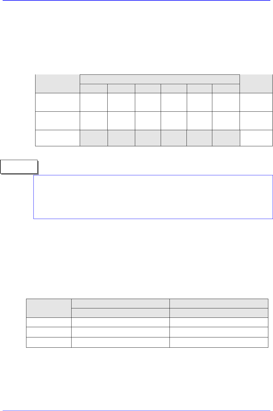
1.2.1. Configuration of the head and vision recognition system
The vision recognition systems of the CP-45F/V and CP-45FS related to the
components placed are as shown in Table 1-1
Table 1-1. Configuration of the Head and Vision Recognition System
Head Structure
Classification
Head 1 Head 2 Head 3 Head 4 Head 5 Head 6
Vision
System
CP-45FV
25mm
Vision
25mm
Vision
25mm
Vision
25mm
Vision
25mm
Vision
25mm
Vision
- 35mm
Vision
CP-45F
25mm
Vision
25mm
Vision
25mm
Vision
25mm
Vision
25mm
Vision
25mm
Vision
CP-45FS
15mm
Vision
15mm
Vision
15mm
Vision
15mm
Vision
15mm
Vision
15mm
Vision
- 35mm
Vision
CP-45FS has six 15mm flying vision cameras for placing the components requiring
precision (0603 Chip, □ 12mm.), and The 20mm , 45mm Stage Vision recognition
systems can be used simply by replacing the upward vision unit. (Please refer to “1.2.2
Applicable component sizes (page 1-3).”)
1.2.2. Applicable component sizes
1.2.2.1. Flying vision recognition system
The sizes of components applicable to this equipment are prescribed in Table 1-2, and is
applicable to general components usage as well.
Table 1-2. Applicable Component Sizes (vision recognition system)
CP-45FV
CP-45FS
Classification
Standard ( FOV 25mm Lens) (FOV 15mm Lens)
Chips 1005 ~ 0603 ~
IC, Connector
~□ 22.0mm , Lead Pitch : 0.5mm ~□ 12.0mm , Lead Pitch : 0.5mm
BGA,CSP
~□ 17.0mm, Ball Pitch : 0.75mm ~□ 12.0mm , Lead Pitch : 0.75mm
Memo

Samsung Component Placer CP-45F(V)/FS Operations Manual
1-4
1.2.2.2. Stage vision recognition system(For CP-45FV /45FS)
Table 1-3. Applicable Component Sizes (Vision Recognition System)
CP-45FV / 45FS
Option
Classification
Standard
FOV35mm
FOV20mm FOV45mm
IC , Connector
~ □ 17mm: 0.3 mm pitch
~ □ 32mm: 0.4 mm pitch
~ □ 40mm: 0.5 mm pitch
( MFOV for more than
32mm)
Chips 1005~
~ □ 17mm: 0.3 mm
pitch
~ □ 32mm: 0.4 mm pitch
~ □ 42mm: 0.5 mm pitch
BGA
~ □ 32mm: 1.0mm pitch
~ □ 17mm: 0.5mm
pitch
~ □ 42mm: 1.0mm pitch
1.2.3. The placement precision
The placement precision for applicable components type is shown in Table 1-4, and is
applicable to general components usage as well.
Table 1-4. The placement Precision
Classification
Placement
precision
Remarks
Chip 0603
Chip 1005
± 0.08
± 0.1
FOV15mm Flying vision (CP-45FS)
± 0.065 FOV25mm Flying Vision(□ 25mm: 0.5 pitch)
QFP
± 0.040 FOV35mm Stage Vision(□ 17mm: 0.3 pitch)
± 0.065 FOV25mm Flying Vision(□ 17mm: 0.75 pitch)
BGA
± 0.080 FOV35mm Stage Vision(□ 32mm: 1.0 pitch)
± 0.065 FOV22mm flying Vision(□ 22mm: 0.5mm pitch)
Connector
± 0.05 FOV35mm Stage Vision(□ 32mm: 0.65mm pitch)
1.2.4. The pick & place cycle time
The descriptions given below refer to the best performance that can be obtained from the
pick & place cycle time. The actual cycle time can vary depending on the size of PCB,
frequency of the nozzle replacement, etc.